Industrial vacuum tank vehicle

A technology of vacuum tanks and automobiles, which is applied in the direction of motor vehicles, goods transport vehicles, and vehicles used for freight transportation. It can solve the problems of heavy vehicle weight, reduced transportation capacity of a single vehicle unit, and heavy load of the filtration system, so as to simplify the overall layout. Avoid high temperature burning and enhance the effect of filtration performance

Active Publication Date: 2012-07-25
长沙凯瑞重工机械有限公司
View PDF4 Cites 0 Cited by
  • Summary
  • Abstract
  • Description
  • Claims
  • Application Information

AI Technical Summary

Problems solved by technology

However, the following problems generally exist in this kind of products: (1) The products are mainly used for the treatment of dust removal dust in metallurgical dust removal systems. The fluidized bed of the unloading system is abnormally damaged by the vacuum pump of key components; (2) affected by the specific gravity and particle size of the dust at the same time, the vacuum suction and positive pressure discharge performance of the product is extremely unstable; (3) the product is high-frequency and The requirement of the suction volume per unit time and the heavy load of the filter system lead to unstable filter cleaning performance; (4) Metallurgical dust removal has high temperature properties, and the existing products in use have filter system bags and fluidized bed burnout accidents of the air unloading system (5) The products all adopt two independent systems of vacuum system and air compressor, and there are many power drive systems, and the vehicle is heavy, which reduces the transportation capacity of the single vehicle unit and high energy consumption; (6) The connection of the suction hose is more complicated Difficult, often the joints are not tightly sealed, resulting in loss of suction volume and energy waste

Method used


Image

  • Industrial vacuum tank vehicle
  • Industrial vacuum tank vehicle
  • Industrial vacuum tank vehicle

Examples


Embodiment Construction

[0026] The present invention will be further described in detail below in conjunction with the accompanying drawings and specific embodiments.

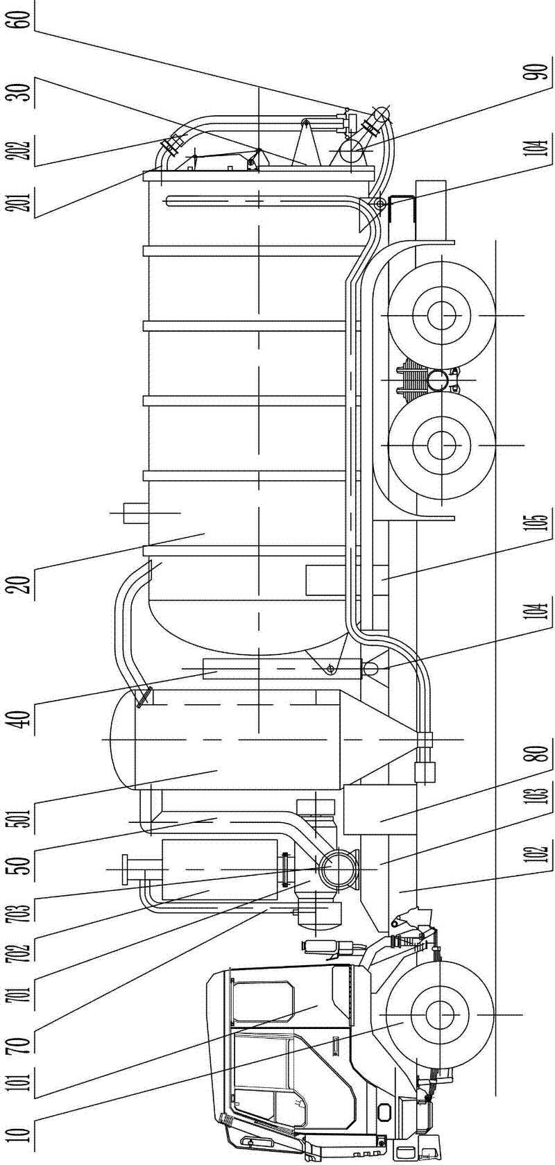
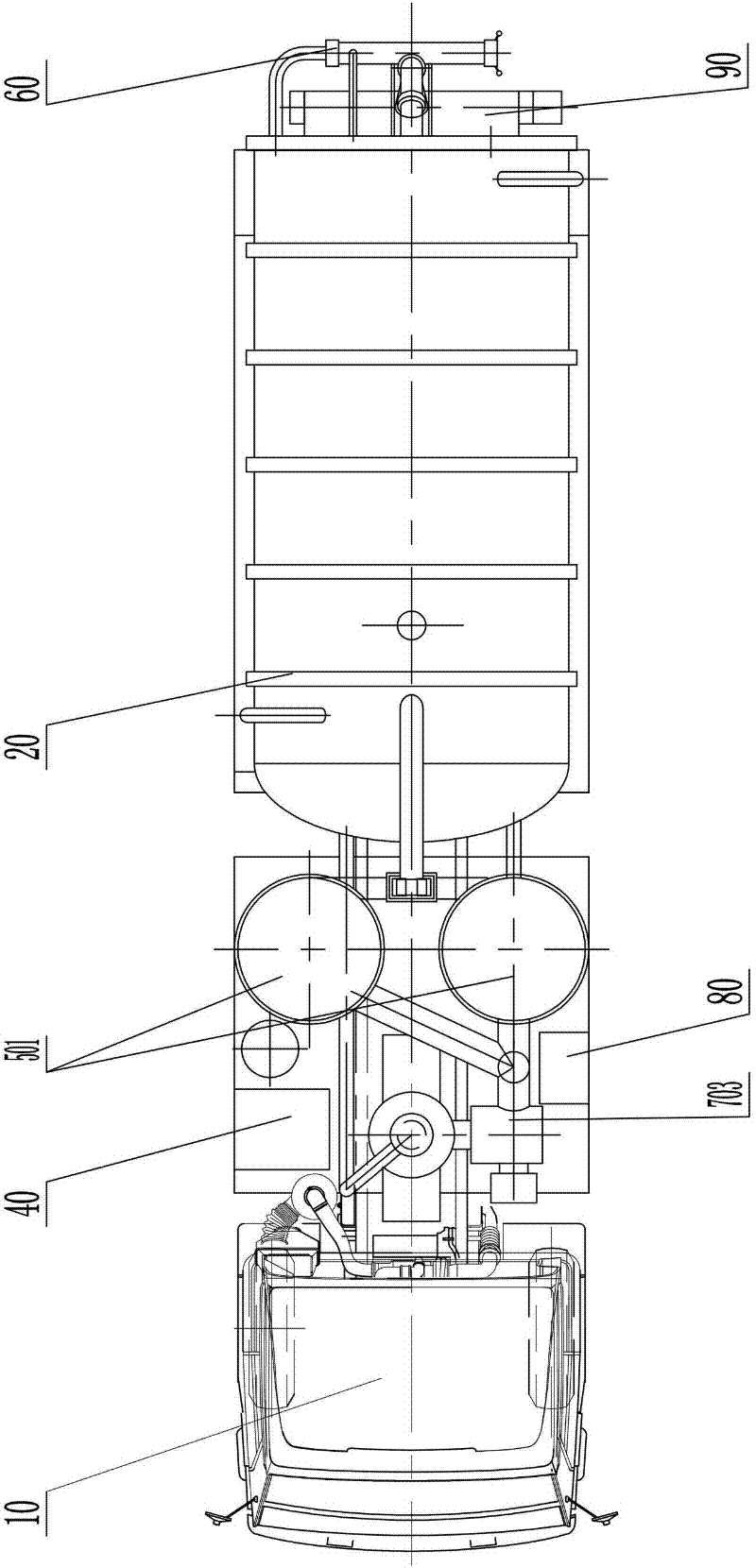
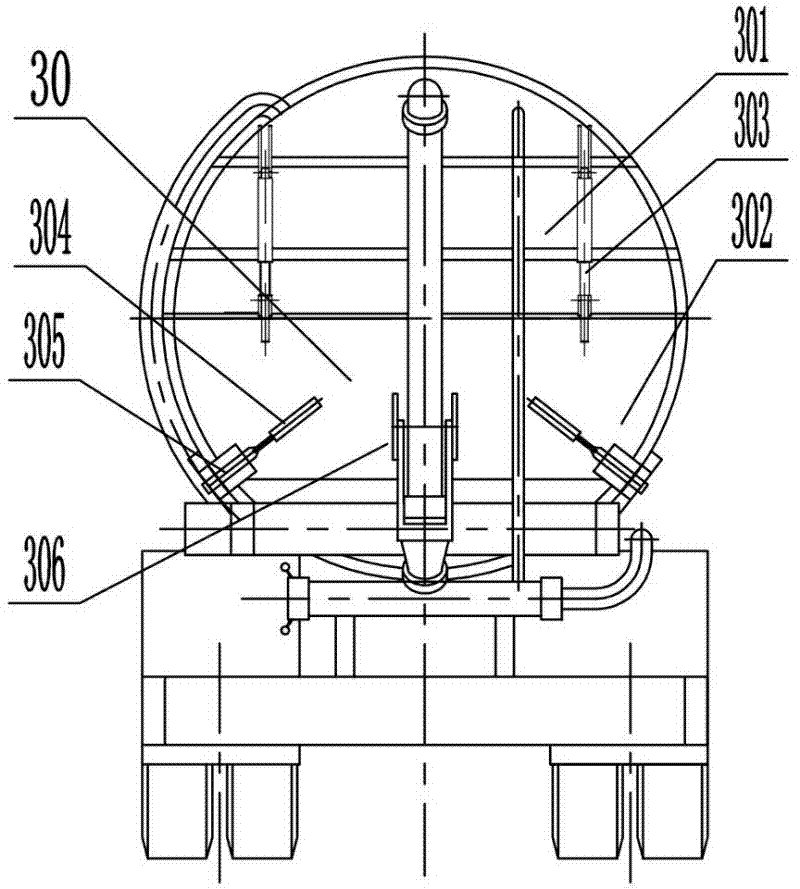
[0027] Such as figure 1 , figure 2 , image 3 with Figure 4 As shown, the industrial vacuum tank vehicle of the present invention includes a chassis 10 and a storage tank 20 installed on the chassis 10, a tailgate assembly 30, a hydraulic dumping assembly 40, a double-circuit cyclone bag combination filter 50, and a pneumatic discharge Device 60, two-way vacuum system 70, control system 80 and screw unloader 90, the rear end of the storage tank 20 away from the cab 101 is hinged on the chassis 10, the front bottom of the storage tank 20 close to the cab 101 is connected to the hydraulic pressure The dump assembly 40 is hinged; the tailgate assembly 30 is installed at the tail end of the material storage tank 20, and the top of the material storage tank 20 tail end is provided with a suction pipe 202, and a 45-degree angle is prov...


PUM


Abstract

The invention discloses an industrial vacuum tank vehicle. The industrial vacuum tank vehicle comprises a chassis, and a material storage tank, a tailgate component, a hydraulic dump component, a dual-loop whirlwind cloth bag combination filter, a pneumatic unloading device, a two-way vacuum system, a control system and an auger stripper which are arranged on the chassis, wherein the tail end, far away from a cab, of the material storage tank is hinged on the chassis; the bottom of the front end, close to the cab, on the material storage tank is hinged with the hydraulic dump component; the tailgate component is arranged at the tail end of the material storage tank; the top part of the tailgate component is provided with a material suction pipe; the material suction pipe is communicated with the two-way vacuum system after passing through the dual-loop whirlwind cloth bag combination filter; the auger stripper is fixed on the lower part of the tailgate component; and the outlet end ofthe auger stripper is provided with the pneumatic unloading device which is communicated with the dual-loop whirlwind cloth bag combination filter through a pipeline. The industrial vacuum tank vehicle has the advantages of simple and compact structure, low cost, high environmental protection property, wide application range, high maneuverability, high energy saving property and the like.

Description

technical field [0001] The invention mainly relates to the field of engineering vehicles, in particular to a vacuum tank type transport vehicle. Background technique [0002] Traditional vacuum tank transport vehicles, such as the suction pressure tank vehicle invented by Wuhan Zhongqi Sihuan Special Vehicle Company (patent number: 02290548.0), and the suction pressure delivery invented by Wuhan Yunsheng Special Vehicle Co., Ltd. (patent number: 200520099207.5) Tank cars and vehicle-mounted positive and negative pressure pneumatic conveying equipment invented by Beijing Huiwan (Patent No. 200620167466.1) have been widely used in steel, thermal power generation and other industries. Its working principle is: use vacuum loading technology to suck all kinds of dusty materials into the storage tank, transport them to the designated recovery point by driving, and unload the materials in the storage tank into the In a special storage tower or container, commonly known as "suctio...

Claims


Application Information

Patent Timeline
Patent Type & Authority Patents(China)
IPC IPC(8): B60P3/00B65D90/00B65D90/54B65D90/66
Inventor 张卫东张舒原徐元诗
Owner 长沙凯瑞重工机械有限公司
Why Eureka
Try Eureka