Stress axis fixation method of polarization-maintaining fiber

A polarization-maintaining optical fiber and axis-fixed technology, which is applied in the direction of polarized optical fiber, clad optical fiber, light guide, etc., can solve the problems of large extinction ratio loss, difference in stress direction, and reduced device performance, so as to improve accuracy and increase extinction ratio Effect

Active Publication Date: 2012-06-27
上海傲世控制科技股份有限公司
View PDF0 Cites 0 Cited by
  • Summary
  • Abstract
  • Description
  • Claims
  • Application Information

AI Technical Summary

Problems solved by technology

The usual practice now is to observe under a microscope, adjust the orientation of the polarization-maintaining fiber so that the slow axis is parallel to the reference plane, and then bond the polarization-maintaining fiber to the support. However, this parallelism can only be observed with the naked eye, which is difficult to achieve accurate measurement
In addition, since the stress zone cannot have an ideal geometric shape and position, the optical symmetry axis and the actual stress direction are also different.
In this way, it is difficult to ensure the consistency of the polarization direction when the polarization-maintaining fiber is bonded to the fiber support by the general optical axis fixing method, and then coupled with the waveguide, which results in a large extinction ratio loss and greatly reduces the overall Device performance

Method used


Image

  • Stress axis fixation method of polarization-maintaining fiber
  • Stress axis fixation method of polarization-maintaining fiber
  • Stress axis fixation method of polarization-maintaining fiber

Examples


Embodiment Construction

[0021] The features of the present invention and other relevant features will be described in further detail below through embodiments in conjunction with the accompanying drawings, so as to facilitate the understanding of those skilled in the art.

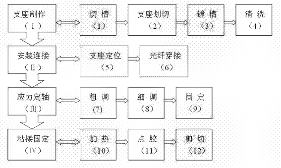
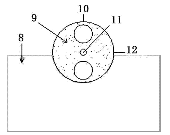
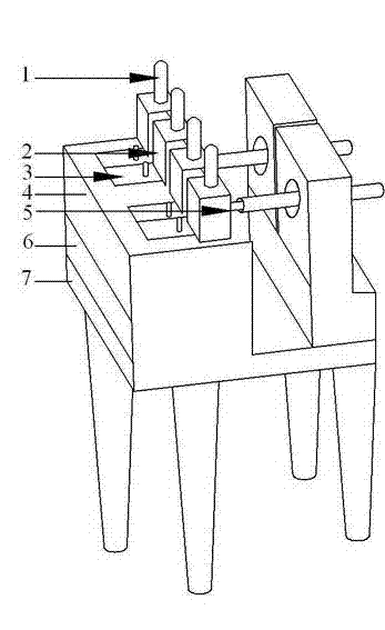
[0022] Such as Figure 1-3 As shown, the labels respectively indicate: positioning pin 1, pressing block 2, card 3, heater 4, adapter 5, heat shield 6, base 7, optical fiber support 8, polarization maintaining optical fiber 9, slow axis 10, core 11, Fast axis 12.

[0023] The basic principle of the present invention is as follows: by passing linearly polarized light with a high extinction ratio into one end of the polarization maintaining fiber 9 and inserting an extinction ratio meter into the other end, the extinction ratio can be displayed in real time. Then remove the organic cladding of the polarization-maintaining fiber near the end of the extinction ratio meter, and apply a certain pressure to it. If the direction of the p...


PUM


Abstract

The invention relates to the technical field of optical waveguide and polarization-maintaining fiber coupling in integrated optical devices, in particular to a stress axis fixation method of a polarization-maintaining fiber before the polarization-maintaining fiber is bonded with a fiber support. The method comprises the following steps of: (a) connecting an extinction ratio meter to one end of the polarization-maintaining fiber and inputting linearly polarized light with a high extinction ratio to the other end of the polarization-maintaining fiber; (b) applying normal force to the polarization-maintaining fiber in any directions and changing the size of the normal force; and (c) observing a numerical value displayed by the extinction ratio meter to determine the slow axis direction of the polarization-maintaining fiber. The method has the advantages that by applying the working principle to carrying out axis fixation of the polarization-maintaining fiber, the method greatly improvesthe accuracy of axis fixation, thereby further improving the extinction ratio of the devices.

Description

technical field [0001] The invention relates to the technical field of optical waveguide and polarization-maintaining optical fiber coupling in integrated optical devices, in particular to a method for stress-fixing a polarization-maintaining optical fiber before being bonded to an optical fiber support. Background technique [0002] The polarization-maintaining fiber is in a radial direction of the preform, and two regions are removed symmetrically with respect to the core diameter of the fiber or replaced with boron glass, because boron glass is better than the fiber cladding SiO 2 It has a large expansion coefficient. After being drawn into an optical fiber, in the two stress regions of the boron glass, a large stress is generated on the core diameter and the refractive index changes. At this point, the fiber behaves like an anisotropic birefringent crystal. [0003] In the manufacture of integrated optical fiber gyroscope multifunctional chip, it is necessary to couple ...

Claims


Application Information

Patent Timeline
Patent Type & Authority Patents(China)
IPC IPC(8): G02B6/024G02B6/245
Inventor 王若东曹泽煌杨凯翔
Owner 上海傲世控制科技股份有限公司
Why Eureka
Try Eureka