Eureka AIR delivers breakthrough ideas for toughest innovation challenges, trusted by R&D personnel around the world.

Double control fuel mixing chamber and separation flame plate

A technology of fuel mixing and flame disc, which is applied in combustion chambers, continuous combustion chambers, combustion methods, etc., can solve the problems of rich oil, large or small air flow, easy carbon deposition, etc., and achieve high temperature, small volume, and easy The effect of carbon deposition

Inactive Publication Date: 2010-12-22
叶民主
View PDF0 Cites 6 Cited by
  • Summary
  • Abstract
  • Description
  • Claims
  • Application Information

AI Technical Summary

Problems solved by technology

Since there is no valve in the flame tube to adjust the compressed air flow rate and separate the flame plate, the air from the compressor can only maintain a certain flow rate, and the air flow rate cannot be manually controlled. When there is a large amount of oil, it is easy to get rich , when there is small oil, it is easy to run out of oil
Since the head section of the flame tube is both a mixing chamber and a combustion chamber, there are factors of instability of the fire source
In addition, because the atomized fuel is heated first, then mixed and burned, there is a problem of easy carbon deposition

Method used


Image

  • Double control fuel mixing chamber and separation flame plate
  • Double control fuel mixing chamber and separation flame plate

Examples


Embodiment Construction

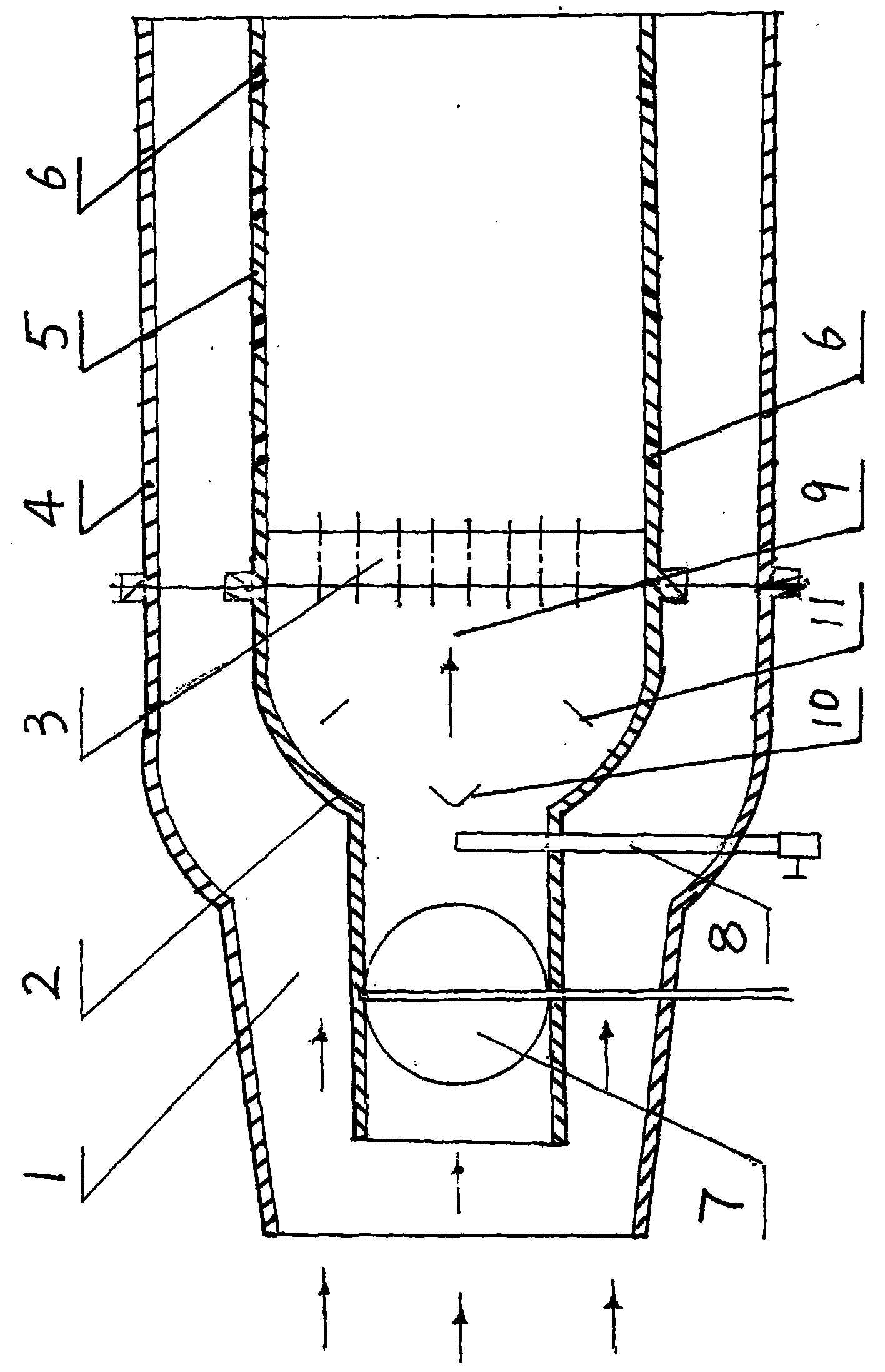
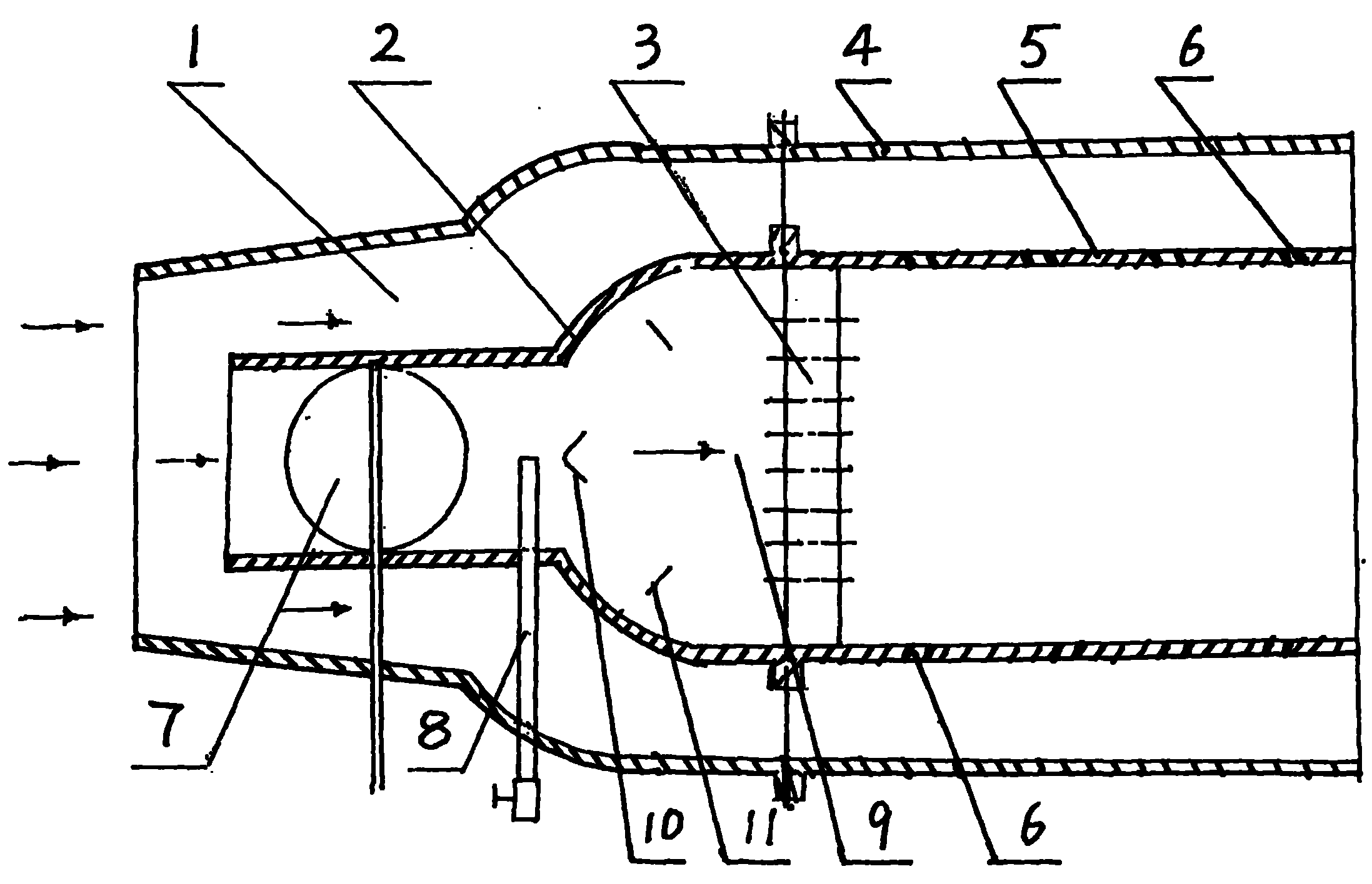
[0012] Such as figure 1 shown. The present invention is composed of a mixing chamber 2, a valve 7 with adjustable compressed air flow rate, a gas dividing plate 10, a gas gathering plate 11, and a fuel pipe 8. The mixing chamber 2 is made of conductive material. Flame tube 5 is made of high temperature resistant material. The valve 7 is located at the neck of the mixing chamber 2 to adjust the intake volume of the high-speed compressed air in the mixing chamber so that the gas and fuel value can reach 1, and the high energy speed and low speed can be controlled. The bell mouth section of the mixing chamber 2 is a mixing area, and two gas side discs 10 are arranged at the front and rear positions of the central axis of the mixing chamber 2. The gas side discs 10 are conical cover bodies, which can guide the airflow to the surroundings. The converging disc 11 is an annular conical cover, connected to the mixing chamber 2 through a bracket, and matched with two gas side discs ...


PUM


Abstract

The invention is named a turbine engine fuel mixing chamber with a separation flame plate, belongs to the technical field of turbine engines, and mainly solves the problems that air velocity cannot be controlled and a fixed-point fire source cannot be realized better in the conventional engine. The double control fuel mixing chamber is mainly characterized by comprising the mixing chamber and the separation flame plate which is connected with an outlet end of the mixing chamber; an inlet end of the mixing chamber is provided with a valve which can adjust compressed air flow; a wall of the mixing chamber is provided with a fuel pipe which passes through the wall, and a pipe head of the fuel pipe is positioned on a main air flow channel behind the valve; a gas separation tray which guides the air flow to the periphery is arranged on a central axis position of the mixing chamber; and a gas collecting tray which guides the air flow to the center is arranged around the inner wall of the mixing chamber. The double control fuel mixing chamber and the separation flame plate have the characteristics that: air is mixed with fuel oil at a low temperature, then the mixture is heated and finally combusted at a fixed point in the mixing chamber, and are mainly used for the turbine engines of aviation, navigation, electricity generation, land transportation and the like.

Description

technical field [0001] The invention belongs to the technical field of turbine engines. In particular, it relates to a dual-control fuel mixing chamber and a separate flame plate for a turbine engine operating compressed air at high speed. Background technique [0002] At present, aviation gas turbine engines have only one combustion and mixing chamber, such as a cylindrical combustor, which is composed of a combustor jacket, a flame tube, and a nozzle. The atomized fuel is blended and burned, and continues to be mixed and burned with the unburned atomized fuel at the rear of the flame tube, and the temperature of the gas is reduced. Since there is no valve in the flame tube to adjust the compressed air flow rate and separate the flame plate, the air from the compressor can only maintain a certain flow rate, and the air flow rate cannot be manually controlled. When there is a large amount of oil, it is easy to get rich , When there is small oil, it is easy to be poor in oi...

Claims


Application Information

Patent Timeline
Patent Type & Authority Applications(China)
IPC IPC(8): F23R3/28
Inventor 叶民主
Owner 叶民主
Why Eureka
Eureka Blog
Learn More