
Thin walled tube welding method

A welding method and technology for thin-walled pipes, applied in welding equipment, auxiliary welding equipment, welding/cutting auxiliary equipment, etc., can solve problems such as low strength and difficult positioning

Inactive Publication Date: 2010-12-22
王浩东
View PDF0 Cites 7 Cited by
  • Summary
  • Abstract
  • Description
  • Claims
  • Application Information

AI Technical Summary

Problems solved by technology

[0002] The welding of existing thin-walled pipes is directly welded after butt joint of two thin-walled pipes. Due to the thin wall of the pipes, it is not easy to position during direct butt welding, resulting in low welding strength.

Method used


Image

  • Thin walled tube welding method
  • Thin walled tube welding method

Examples


Embodiment Construction

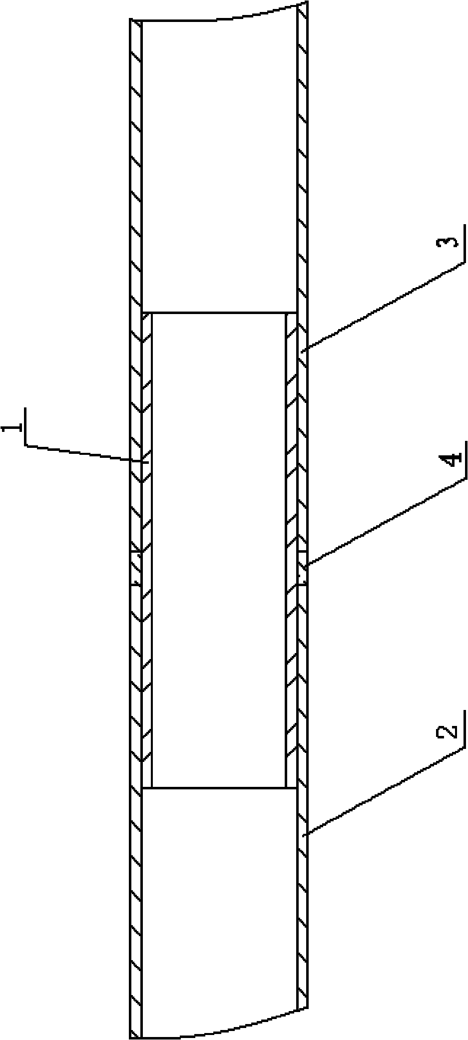
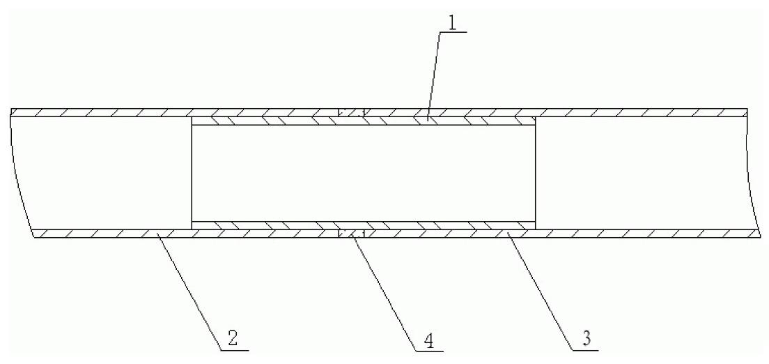
[0011] See figure 1 , which includes a liner 1, two thin-walled pipes 2, 3, the two ends of the liner 1 are respectively loaded into the inner holes of the two thin-walled pipes 2, 3 to be welded, and silver welding wire 4 is welded circumferentially between the liner 1 and the two thin-walled pipes. 2, 3 exposed places. The two ends of the liner 1 are screwed into the inner holes of the two thin-walled pipes 2 and 3 that need to be welded, or the two ends of the liner 1 are plugged into the inner holes of the two thin-walled pipes 2 and 3 that need to be welded.


PUM


Abstract

The invention discloses a thin walled tube welding method. The method has the characteristics of simple contraposition and high welding strength when two thin walled tubes are welded. The method is characterized by comprising the following steps of: a, respectively filling the two ends of a liner tube into the inner bores of the two thin walled tubes needing to be welded; b, circumferentially welding the liner tube and the exposed parts of the two thin walled tubes by using silver wires; and c, burnishing a welding seam to make the welding seam smooth.

Description

(1) Technical field [0001] The invention relates to the technical field of thin-walled pipe welding, in particular to a thin-walled pipe welding method. (2) Background technology [0002] The welding of existing thin-walled pipes is all formed by direct welding after butt joint of two thin-walled pipes. Because of the thin wall of the pipes, it is not easy to position during direct butt welding, resulting in low welding strength. (3) Contents of the invention [0003] In view of the above problems, the present invention provides a welding method for thin-walled pipes, which enables simple alignment of two thin-walled pipes during welding and high welding strength. [0004] A kind of thin-walled pipe welding method, its technical scheme is such, it is characterized in that: [0005] a. Install the two ends of the liner into the inner holes of the two thin-walled pipes to be welded respectively; [0006] b circumferentially welding the liner and the exposed parts of the tw...

Claims


Application Information

Patent Timeline
IPC IPC(8): B23K37/00
Inventor 王浩东
Owner 王浩东
Learn More