
New premix burner

一种预混燃烧、燃烧器的技术,应用在燃烧器、气体燃料燃烧器、燃烧方法等方向,能够解决燃烧器难制成等问题,达到气流顺畅、降低排放、火焰稳定的效果

Inactive Publication Date: 2010-12-15
BEKAERT COMBUSTION TECH
View PDF3 Cites 4 Cited by
  • Summary
  • Abstract
  • Description
  • Claims
  • Application Information

AI Technical Summary

Problems solved by technology

In particular, certain shapes of burners are difficult to make serially when made from stainless steel plate or sheet metal

Method used


Image

  • New premix burner
  • New premix burner
  • New premix burner

Examples


Embodiment Construction

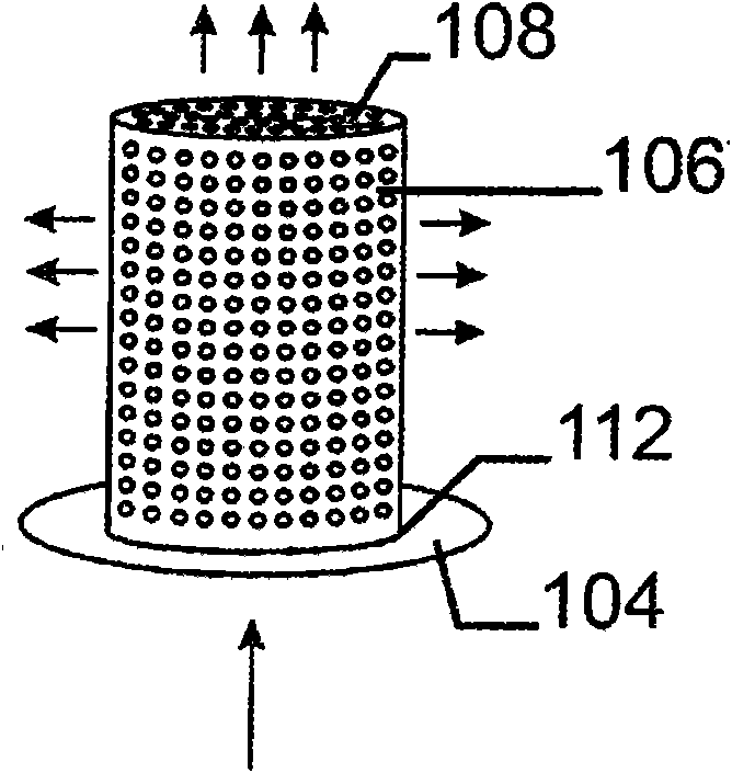
[0048] Figure 1a A cylindrical burner according to the invention is shown comprising a gas supply chamber 102 connected at the bottom to a support 104 . The bracket 104 has a central gas inlet for supplying gas into the gas supply chamber 102 . The gas supply chamber 102 is surrounded by a first burner membrane 106 on its side and a second burner membrane 108 opposite said gas inlet. The second burner membrane 108 is connected to the top of the burner membrane 106 . The burner membrane 106 is connected to the bracket 104 at the bottom. Arrows indicate flames generated in a direction generally perpendicular to the burner surfaces, thereby providing radial air flow at the first combustor diaphragm 106 and axial gas flow at the second combustor diaphragm 108 .

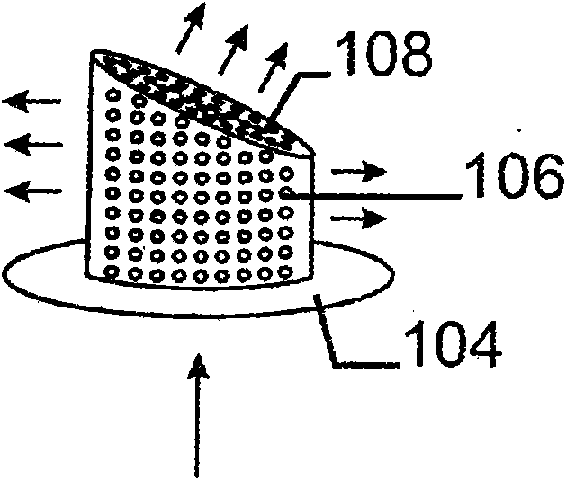
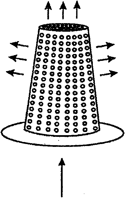
[0049] Figure 1b shows the same Figure 1a The illustrated burner is similar to a cylindrical burner, with the second burner diaphragm 108 forming a plane that intersects the first burner diaphragm 106 at an angle ot...


PUM


Abstract

The present invention provides a gas burner, preferably a premix burner, comprising a support having a central gas inlet port for supply of gas into a gas supply chamber. The gas supply chamber is enclosed by a first metal burner membrane at its side and an end cap opposite to said gas inlet port. The end cap is connected to the top of the first burner membrane. The burner membrane is connected at the bottom to the support through its base section. The end cap is formed by a second burner membrane. The exterior surface of the first burner membrane and the end cap is made of perforated heat-resistant sheet metal plate.

Description

technical field [0001] The present invention provides an improved gas burner for optimum combustion in the confined space of modern heat exchangers. More particularly, the present invention relates to premix gas burners that include an additional active burner surface at the burner end cover. Background technique [0002] Modern heat exchangers have advanced and more compact designs. Due to the limited space available in the combustion chamber of modern heat exchangers, it is necessary to use improved gas burners that provide an optimal combustion surface. [0003] Traditional burners do not burn optimally in modern heat exchangers because the space available in the heat exchanger is not used optimally for the flame generated. This is inherent to the effective burner surface of a gas burner, which is not suitable for the design of the heat exchanger. [0004] The atmospheric burner described in EP 0594262 has a wire mesh wall arranged around the gas / air mixing chamber. H...

Claims


Application Information

Patent Timeline
Patent Type & Authority Applications(China)
IPC IPC(8): F23D14/10F23D14/14
CPCF23D14/10F23D2203/1012F23D14/14F23D14/145
Inventor D·坦恩霍夫
Owner BEKAERT COMBUSTION TECH
Learn More