
Control valve for a camshaft adjuster

A technology for controlling valves and ventilation valves, applied in valve devices, machines/engines, thin material handling, etc., can solve the problems of hindering the relative movement of components, expensive and improved filter manufacturing and assembly, and achieve good purification and enlargement. filter effect

Active Publication Date: 2010-12-15
SCHAEFFLER TECH AG & CO KG
View PDF1 Cites 19 Cited by
  • Summary
  • Abstract
  • Description
  • Claims
  • Application Information

AI Technical Summary

Problems solved by technology

The disadvantage of these solutions is that, due to the additional oil distribution sleeve, there is an increased risk of debris during assembly of the oil distribution sleeve, wherein these debris can enter the pressure medium conduction channel or interfere with components in the following way relative to each other, i.e. the valve is no longer able to fulfill its function
In addition, the application of separate filters is expensive in manufacture and assembly

Method used


Image

  • Control valve for a camshaft adjuster
  • Control valve for a camshaft adjuster
  • Control valve for a camshaft adjuster

Examples


Embodiment Construction

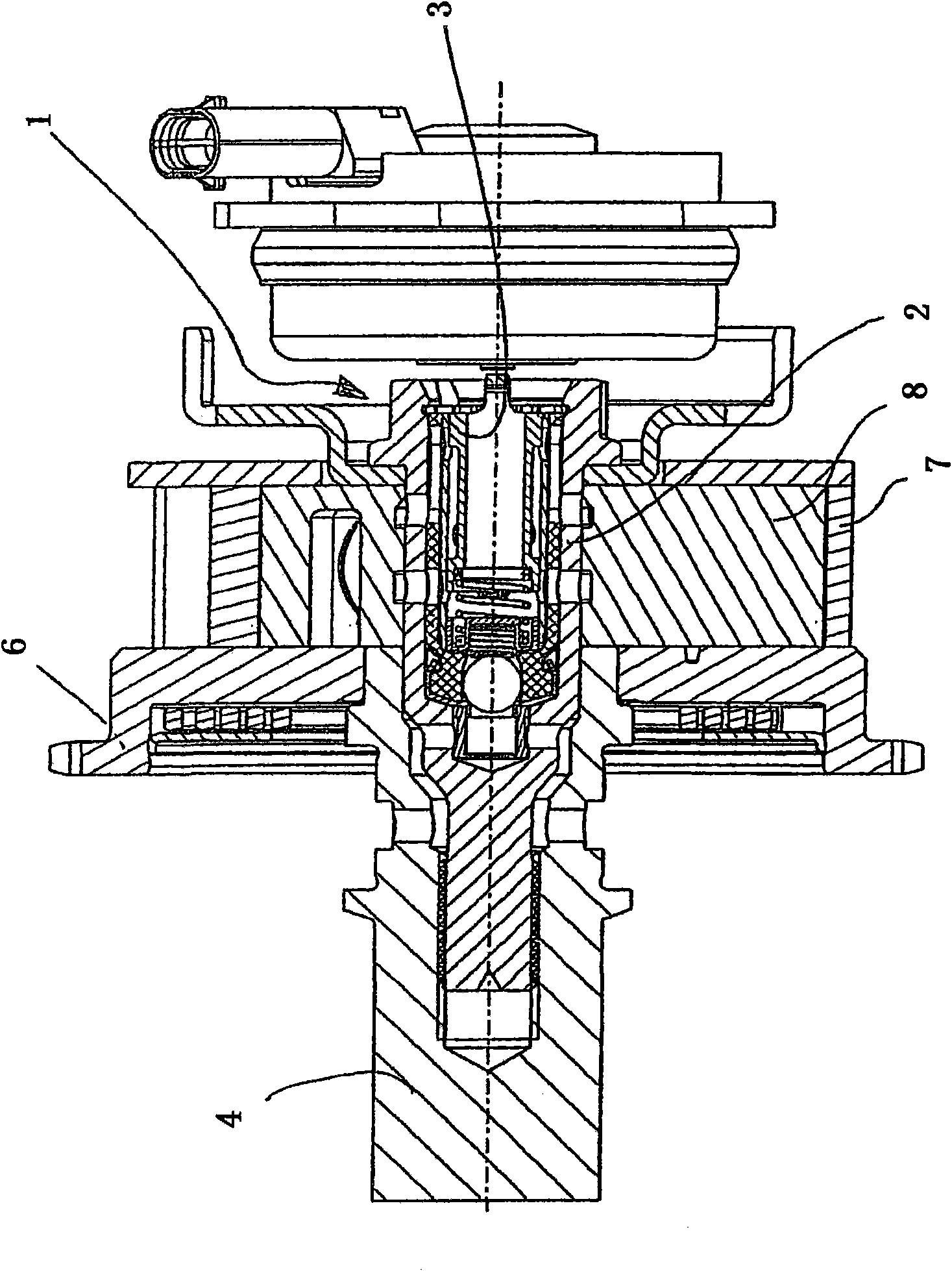
[0020] exist figure 1 A device for variable adjustment of the timing of gas exchange valves of an internal combustion engine is shown in FIG. 2 , which has a transmission wheel 6 which is connected in a rotationally fixed manner to a stator 7 . In addition, a rotor 8 is provided, which is connected in a rotationally fixed manner to the camshaft 4 . The transmission wheel 6 is driven directly or indirectly by the crankshaft of the internal combustion engine. The rotational movement of the drive wheel 6 is then transmitted via the stator 7 to the rotor 8 , so that the camshaft 4 , which is connected in a rotationally fixed manner to the rotor 8 , also rotates. The rotating camshaft 4 then controls the opening and closing times of the gas exchange valves of the internal combustion engine. The adjustment of the control time of the gas exchange valve is then carried out by the relative rotation of the rotor 8 relative to the stator 7 , which is controlled by the control valve 1 ....


PUM


Abstract

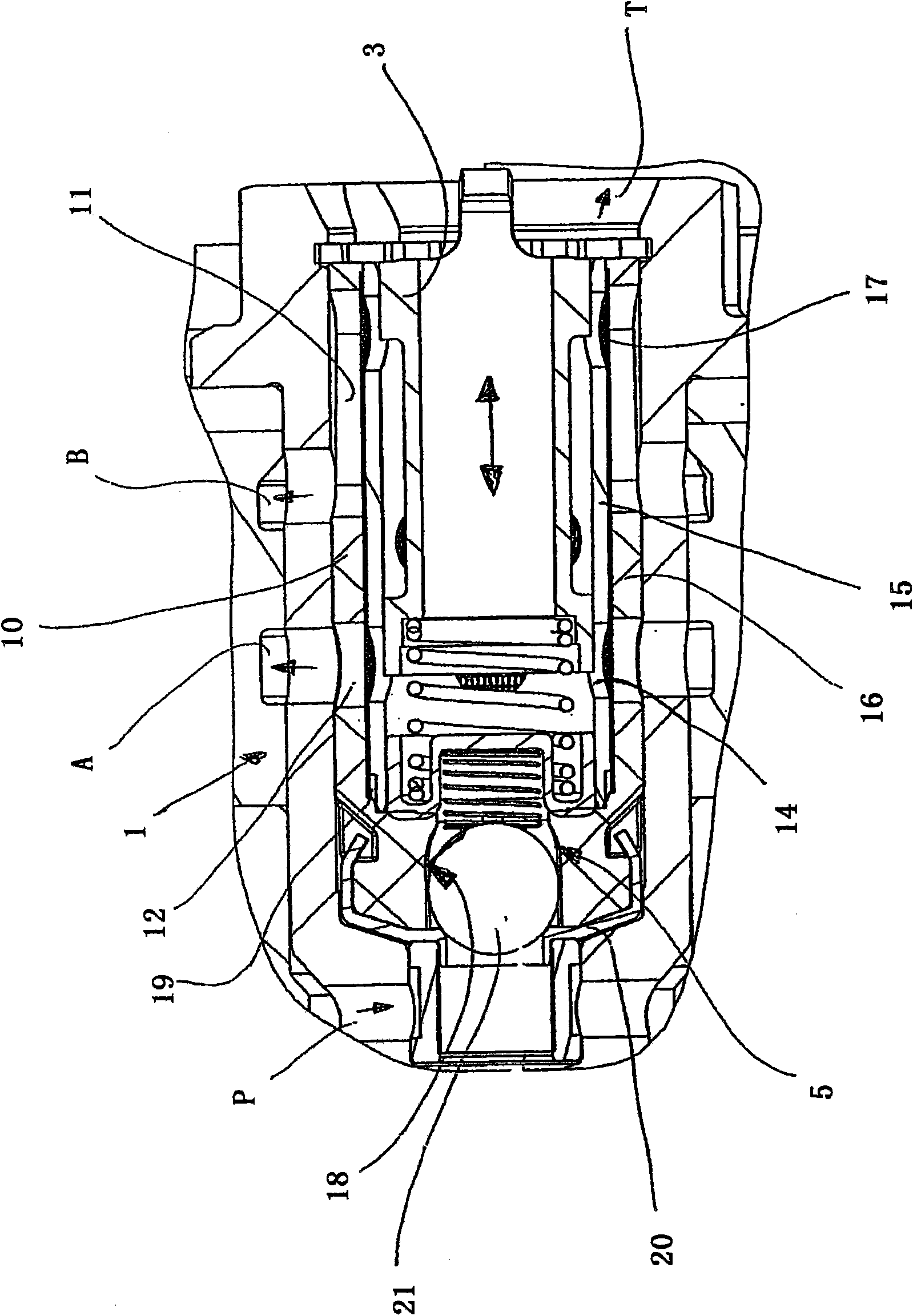
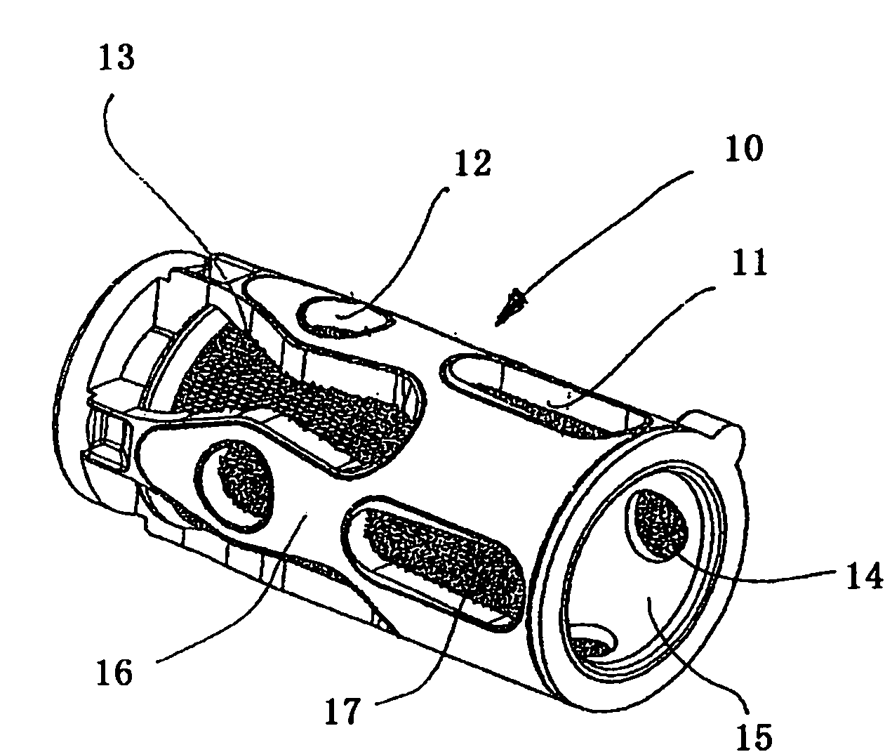
The invention relates to a control valve (1) for a device for the variable setting of the control times of gas exchange valves of an internal combustion engine having a valve housing (2), which is implemented as hollow, and which has at least one inflow connection (P), at least one exhaust connection (T), and at least two working connections (A, B), and a hydraulic medium conduction insert (10), which is disposed in the valve housing (2) and implemented as hollow, having hydraulic medium conduction channels (11, 12, 13, 14), which are disposed in the wall of the hydraulic medium conduction insert (10) and communicate with the working connections (A, B), and a control piston (3), which is disposed in the hydraulic medium conduction insert (10), wherein said hydraulic medium conduction insert (10) has a guide sleeve (15), in which said control piston (3) is guided, said guide sleeve (15) has a plastic encapsulation (16), in which at least two of said hydraulic medium conduction channels (11, 12, 13, 14) are disposed, and a filter fabric (17) is provided between said plastic encapsulation (16) and said guide sleeve (15).

Description

technical field [0001] The invention relates to a control valve according to the preamble of claim 1 for a device for variable adjustment of the timing of a gas exchange valve in an internal combustion engine. Background technique [0002] A generic control valve is known, for example, from DE 10 2005 052 481 A1. In this case, the pressure medium is filtered by means of a separate filter assigned to the inlet channel and / or by using an oil separation sleeve. The disadvantage of these solutions is that, due to the additional oil distribution sleeve, there is an increased risk of debris during assembly of the oil distribution sleeve, wherein these debris can enter the pressure medium conduction channel or interfere with components in the following way relative to each other, ie the valve can no longer fulfill its function. Additionally, the application of separate filters is expensive in manufacture and assembly. Contents of the invention [0003] The object of the presen...

Claims


Application Information

Patent Timeline
Patent Type & Authority Applications(China)
IPC IPC(8): F01L1/344F01L1/34
CPCF01L1/3442F01L1/34F01L2001/3443F01L2820/041F01L2001/34483F01L2001/34433F01L2001/34426F01L1/022F01L2001/3444F01L2001/34479Y10T137/86751Y10T137/8663
Inventor 格哈德·沙伊迪希阿里·巴伊拉克达尔
Owner SCHAEFFLER TECH AG & CO KG
Learn More