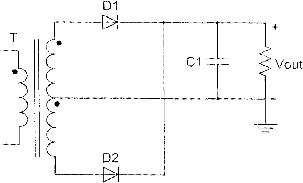
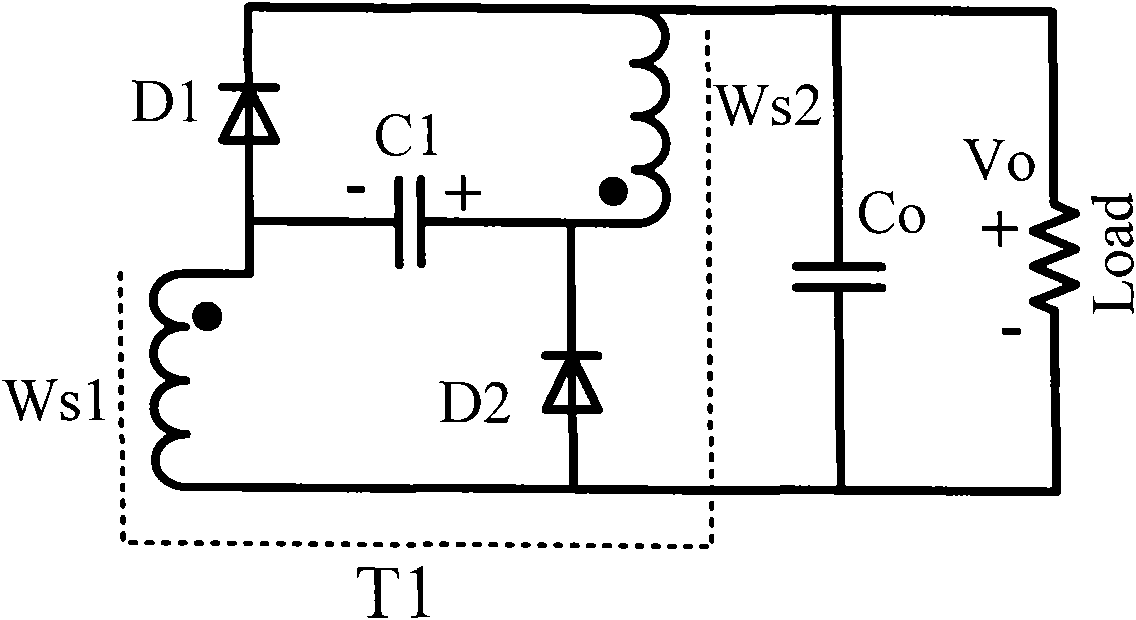
Rectifier circuit for realizing voltage clamp of rectifier tube by using double-power transformer
A technology of power transformer and rectifier circuit is applied in the direction of converting DC power input into DC power output, output power conversion device, and irreversible AC power input into DC power output, etc. It can solve the problems of junction capacitance oscillation of rectifier devices, Achieve the effect of suppressing voltage parasitic oscillation, simplifying winding structure, and improving conduction loss
- Summary
- Abstract
- Description
- Claims
- Application Information
AI Technical Summary
Problems solved by technology
Method used
Image
Examples
Embodiment Construction
[0029] The present invention will be described in detail below in conjunction with specific embodiments with reference to the accompanying drawings.
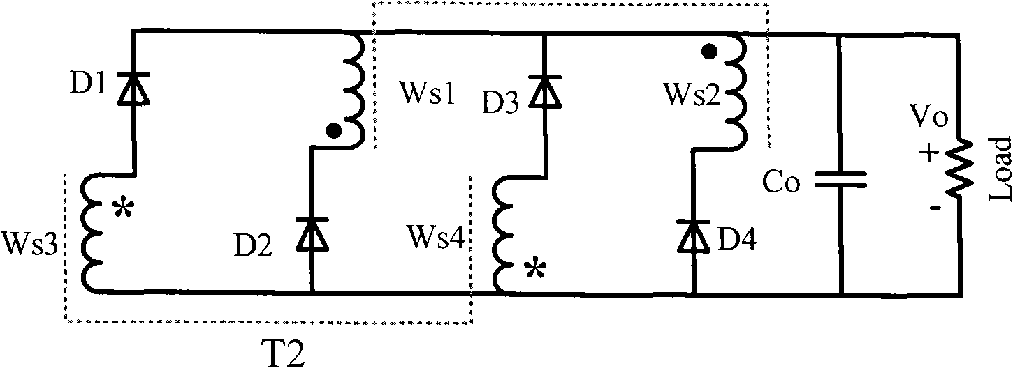
[0030] refer to Figure 4 , a rectifier circuit for rectifier tube voltage clamping with dual power transformers, including two power transformers and four rectifier diodes, the power transformers are two center-tapped rectifiers with one primary winding and two secondary windings respectively structure; in the power transformer, define the terminal with the same name of the transformer winding as the positive terminal and the other as the negative terminal, then: the cathode of the first rectifier diode D1, the negative terminal of the first secondary winding Ws1 of the first power transformer T1 terminal, the cathode of the third rectifier diode D3, and the positive terminal of the second secondary winding Ws2 of the first power transformer T1 are all connected to the positive terminal of the output filter capacitor Co; the po...
PUM
 Abstract
Description
Claims
Application Information
 - R&D Engineer
- R&D Manager
- IP Professional
- Industry Leading Data Capabilities
- Powerful AI technology
- Patent DNA Extraction
Browse by: Latest US Patents, China's latest patents, Technical Efficacy Thesaurus, Application Domain, Technology Topic, Popular Technical Reports.
© 2024 PatSnap. All rights reserved.Legal|Privacy policy|Modern Slavery Act Transparency Statement|Sitemap|About US| Contact US: help@patsnap.com


