
Method for graphically representing network topological objects and network topological object relationships in network planning

A technology of network topology and network planning, applied in the field of logical structure, it can solve the problems of various types of end-to-end service connection protection and restoration, complex and changeable connections and routing relationships, and a large number of end-to-end service connections. Intuitive and concise effect

Inactive Publication Date: 2010-12-15
FENGHUO COMM SCI & TECH CO LTD
View PDF0 Cites 20 Cited by
  • Summary
  • Abstract
  • Description
  • Claims
  • Application Information

AI Technical Summary

Problems solved by technology

Therefore, the representation of network topology objects and their relationships is also relatively easy
[0004] However, due to the more use of mesh network (mesh network) networking in ASON networks, the network scale continues to expand.
This brings about two problems: first, the number of network topology objects that need to be represented in the network topology structure is large, and the relationship between network topology objects is also more complicated; second, the number of end-to-end service connections (Connections) in the network is huge , there are many types of protection and restoration of end-to-end business connections (Connections), and the connections and their routing relationships are also complex and changeable
Effectively establishing this mathematical model will achieve twice the result with half the effort for software implementation, otherwise it will greatly reduce the performance of planning software

Method used


Image

  • Method for graphically representing network topological objects and network topological object relationships in network planning
  • Method for graphically representing network topological objects and network topological object relationships in network planning
  • Method for graphically representing network topological objects and network topological object relationships in network planning

Examples


Embodiment Construction

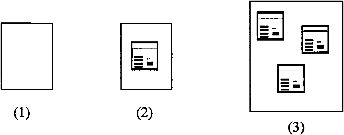
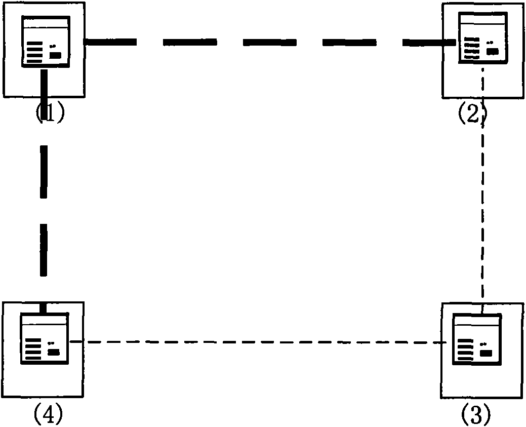
[0044] The present invention will be described in further detail below in conjunction with the accompanying drawings.

[0045]The invention firstly analyzes the objects contained in the SDH / ASON network planning, and determines the relationship between the objects. Then use the graph theory algorithm to build an undirected graph. And expand the composite object on the basis of the undirected graph to meet the requirements of the object model in network planning. The present invention adopts the object-oriented method analysis to know that in the ASON network topology, the network objects involved include: site (Site), node (Node), optical cable (i.e. OLG, Optical LinkGroup, also known as optical fiber pair group), optical fiber (Fiber), shared risk link group (SRLG, SharedRisk Link Group), end-to-end business connection (Connection), business routing (Route). The traditional SDH network objects also include: linear multiplex section protection (MSP, MultiplexSection Protecti...


PUM


Abstract

The invention relates to a method for graphically representing network topological objects and network topological object relationships in network planning. The logical topological structure of a physical network is represented in a topological graph drawing area in planning software by the following operation steps: 1, drawing a station and nodes; 2, drawing an optical cable between two nodes; 3, drawing an optical fiber pair on the optical fiber; 4, drawing end-to-end service connection between the two nodes; 5, drawing a shared risk link group; 6, creating linear multiplex section protection; 7, creating a ring; and 8, creating service route. In the method for graphically representing the network topological objects and network topological object relationships in network planning, the graphical representation mode is direct, simple, clear and complete, all network topological objects in an SDH / ASON network are covered basically, and thus, it is relatively easy to define a mathematic model required by the operation of the planning software on this basis, and a mathematic foundation is provided for the operation of the software.

Description

technical field [0001] The invention relates to the logical structure of the network topological structure in software, in particular to a graphical representation method of network topological objects and their relationships in network planning. Background technique [0002] Currently, an Automatic Switched Optical Network (ASON) that combines switching technology and optical transport technology has been recognized by the industry as the development direction of the optical transport network. As the ASON network planning service platform, ASON network planning software has been paid more and more attention by equipment manufacturers and operators, and high requirements have been put forward for this kind of software. Intuitive, clear and easy to use, etc. [0003] In the network topology structure of a traditional SDH (Synchronous Digital Hierarchy, Synchronous Digital Hierarchy) network, network topology objects mainly exist in the form of protection rings, with few type...

Claims


Application Information

Patent Timeline
IPC IPC(8): G06F17/50G06F3/048H04L12/24G06F3/0481
Inventor 张亨学
Owner FENGHUO COMM SCI & TECH CO LTD
Learn More