
Reflector for area light source with emergent surface area of at least 10mm<2>

A technology of reflectors and surface light sources, applied in reflectors, components of lighting devices, lighting devices, etc., can solve problems such as waste of light energy, light pollution, and obstruction of light emission in lamps, and achieve flexible light distribution, high efficiency, and The effect of less invalid light

Active Publication Date: 2010-12-15
TSINGHUA UNIV
View PDF4 Cites 3 Cited by
  • Summary
  • Abstract
  • Description
  • Claims
  • Application Information

AI Technical Summary

Problems solved by technology

The size of the traditional surface light source is huge, and the light emitting surface area is generally greater than 10mm 2 , it is difficult to carry out light distribution when designing the optical system, and because of the large size of the light source itself and the 360-degree light emission, the light source will hinder the light emission from the lamp, which makes it more difficult to design an efficient and flexible optical system with light distribution
Therefore, the light distribution of the traditional surface light source reflector can only form a simple circular or elliptical light distribution, and there are many problems that the illuminance or brightness distribution is not uniform enough, and a large amount of invalid light outside the target range is irradiated. There is a phenomenon that part of the light is reflected to the light source and absorbed by the light source, and part of the light is reflected to the target plane after two or more reflections. The light utilization rate is generally only 40-45%, so the efficiency of the lamp is low, resulting in the loss of light energy. Waste, poor lighting effects, and even serious problems such as glare and light pollution

Method used


Image

  • Reflector for area light source with emergent surface area of at least 10mm&lt;2&gt;
  • Reflector for area light source with emergent surface area of at least 10mm&lt;2&gt;
  • Reflector for area light source with emergent surface area of at least 10mm&lt;2&gt;

Examples


Embodiment Construction

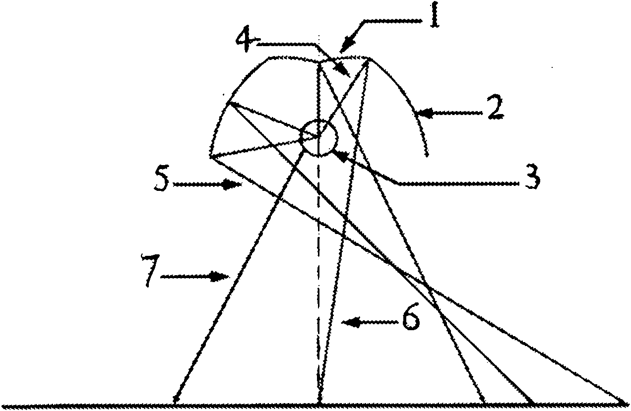
[0033] A reflector for a large-scale surface light source, which consists of two parts: the center and the side: the central part of the reflector reflects the light emitted by the surface light source away from the target plane to the target under the condition of avoiding light source absorption and multiple reflections inside the reflector On the plane; the light reflected by the side part of the reflector is superimposed with the light reflected by the central part and the light emitted by the light source that is directly irradiated on the target plane without the reflector to form an illuminance distribution that meets the predetermined requirements.

[0034] The central part of the reflector is composed of a curve rotating around the central axis of the system; the curve includes but not limited to asymptotes, macroelliptic lines and their combinations; the light reflected by the central part of the reflector is on the target plane An illuminance distribution with centra...


PUM


Abstract

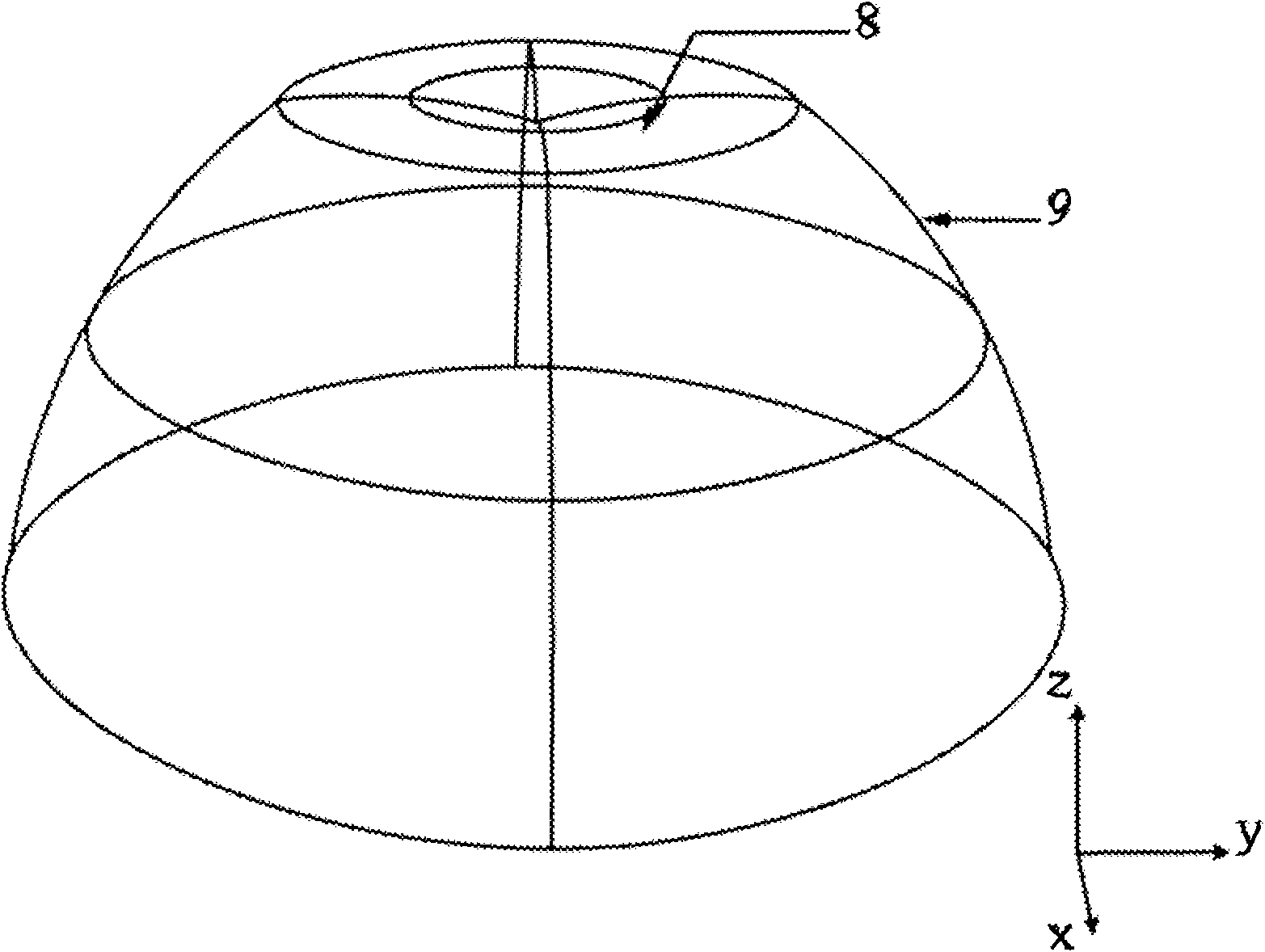
The invention relates to a reflector for an area light source with emergent surface area of at least 10mm<2>, which belongs to the technical field of illuminating lamps. The reflector is characterized by being bowl shaped inverted on a plane and comprises a central part as a bowl bottom and a side part as a bowl side; the central part is formed in such a way that a curve rotates along a central shaft of the bowl; the reflected light forms illumination distribution with central rotational symmetry on a target plane; the side part comprises a three-dimensional free continuous curve surface and can be also formed by discontinuously splicing the three-dimensional free strip curve surfaces; each strip curve surface is independent and continuous; and light distribution formed by the side part, light distribution formed by the central part and the distribution of light which is emitted by the area light source and directly formed without the processing of the reflector are superposed for compensation so as to realize any given light distribution. The invention has the advantages of high luminous efficiency, flexible light distribution and less invalid light.

Description

technical field [0001] The invention relates to a reflector structure of a surface light source, belonging to the technical field of lighting fixtures. Background technique [0002] At present, the most widely used light sources are generally surface light sources, such as high-pressure sodium lamps and electrodeless lamps. These surface light sources generally have high light efficiency, generally 90-140lm / w, but because they emit light at 360 degrees, the utilization efficiency of light energy directly using these light sources is very low, only about 30%, so these light sources usually need to design reflection It is only through the filter that most of the light can be irradiated to the designated area to achieve higher light utilization. [0003] In addition to light effect, another practical problem is the problem of light distribution. Different lighting environments require lighting fixtures with different light distributions. For example, in road lighting, the li...

Claims


Application Information

Patent Timeline
Patent Type & Authority Applications(China)
IPC IPC(8): F21V7/04
Inventor 罗毅曹亮亮韩彦军
Owner TSINGHUA UNIV
Learn More