


Quick Research
Generate reliable direction feasibility study reports for your R&D in just a few steps.

Technical Q&A
Discover and master advanced knowledge NOW. Basics, ideas, possibilities, all at once.

Find Solutions
As an expert in R&D theories, this can generate solutions to your technical problems instantly.

Evaluate Feasibility
Analyze your overall solution with one click, know your potential R&D risks in advance.

Monitor Landscape
Get weekly tech updates, stay abreast of the latest tech innovations and key insights.
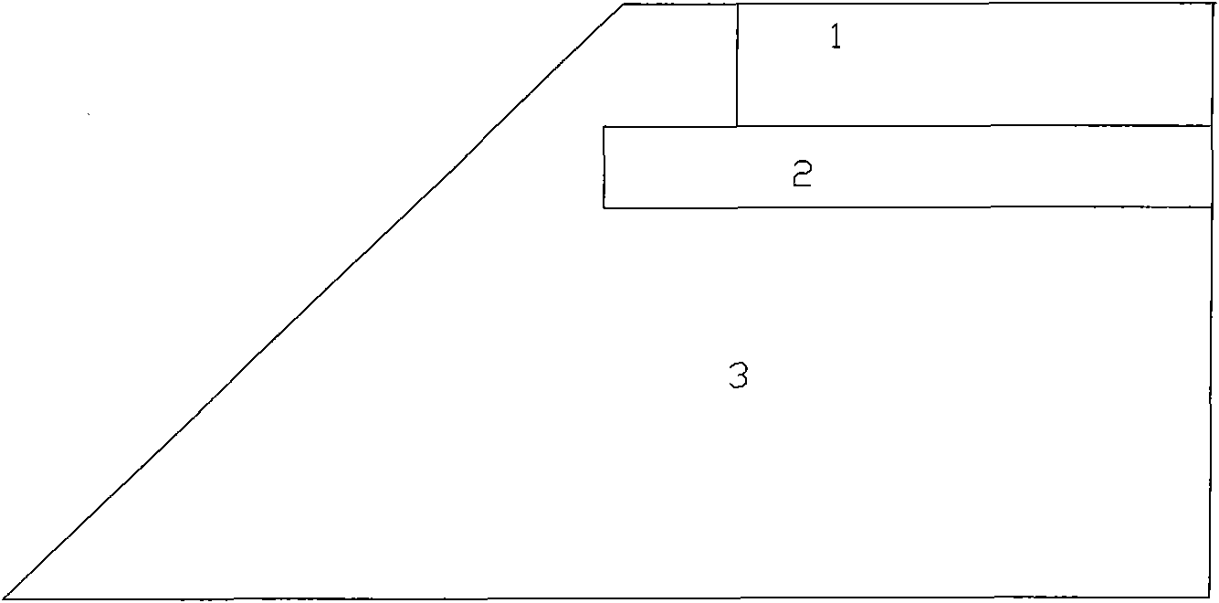
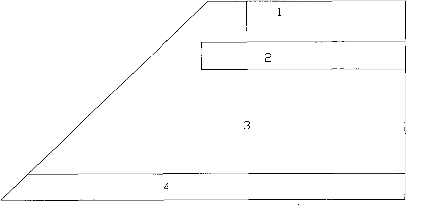
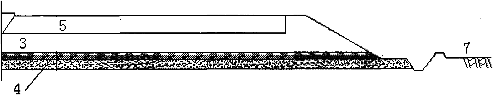
Low embankment structure in phreatic high slity soil region and construction method thereof
A construction method and technology of silty soil, applied in roads, roads, buildings, etc., can solve problems affecting the implementation of low embankments
- Summary
- Abstract
- Description
- Claims
- Application Information
AI Technical Summary
Problems solved by technology
Method used
Image

Examples
Embodiment 1
[0049] The implementation of the Rugao Section RG7 bid section of the 204 National Highway Extension Project in Nantong area is taken as an example to illustrate the present invention below.
[0050] Nantong area is located in the accumulation plain of the Yangtze River Delta. Geological survey found that: the area where the RG7 bid section of Rugao section of the 204 national highway expansion project in Nantong area is located is a modern sedimentary soft soil layer, and the upper layer is mainly silty soil, mostly gray-yellow, yellow-gray, gray sandy low liquid limit Silty soil and silty sand, the lower layer is dominated by silty clay. The water level observation hole set at K821+880 shows that the average groundwater level elevation is 4.55m, and the height from the original ground is 0.47m.
[0051] (1) Capillary water treatment method under low embankment
[0052] Due to the shallow groundwater level, the embankment is within the influence range of capillary water, an...
Embodiment 2
[0071] The present invention is specifically described by taking the implementation of the K7+860~K9+500 section of Jiangsu Xu (zhou) Su (qian) Expressway as an example.
[0072] The project is located in the northeast of the Subei Plain, and the landform units are alluvial plains and piedmont residual slope landform units, forming strata dominated by low liquid limit silt and low liquid limit clay. Especially in the surface layer of the yellow flood plain of the abandoned Yellow River, the low liquid limit silt and silty sand account for a large proportion, and most of them are in a loose state. The groundwater level along the line is 0.7-1.8m underground, the water level is relatively high, and the medium-fine sand is in a saturated state .
[0073] (1) Capillary water treatment method under low embankment
[0074] The buried depth of groundwater in this low-liquid-limit silt area is 0.7-1.8m, and the embankment is within the influence range of capillary water. A layer of w...
PUM
| Property | Measurement | Unit |
|---|---|---|
| thickness | aaaaa | aaaaa |
| thickness | aaaaa | aaaaa |
| height | aaaaa | aaaaa |
Abstract
Description
Claims
Application Information
 - R&D Engineer
- R&D Manager
- IP Professional
- Industry Leading Data Capabilities
- Powerful AI technology
- Patent DNA Extraction
Browse by: Latest US Patents, China's latest patents, Technical Efficacy Thesaurus, Application Domain, Technology Topic, Popular Technical Reports.
© 2024 PatSnap. All rights reserved.Legal|Privacy policy|Modern Slavery Act Transparency Statement|Sitemap|About US| Contact US: help@patsnap.com