
Giant undersea salvage grab bucket

A seabed salvage and grab technology, which is applied in ship salvage, ship, transportation and packaging, etc., can solve the problems of heavy lifting capacity of the grab, self-heavy shipwreck, heavy shipwreck, etc., and achieve the effect of improving economic benefits and efficiency

Inactive Publication Date: 2010-12-15
SHANGHAI MARITIME UNIVERSITY
View PDF6 Cites 3 Cited by
  • Summary
  • Abstract
  • Description
  • Claims
  • Application Information

AI Technical Summary

Problems solved by technology

[0005] The purpose of the present invention is to solve the problem of seabed salvage of sunken ships: due to the complex operating conditions of seabed salvage of sunken ships, there is often nothing that can be done for relatively large sunken ships, because the dead weight of the sunken ship is very large, plus the effect of seabed sand and water pressure, making The sunken ship is even heavier, even if a large floating crane is used, it will not help. For a sunken ship with thousands of tons, grabs can hardly do anything; in view of this situation, to solve the problem of salvage of the sunken ship:
[0006] First of all, the grab has a huge lifting capacity, which can salvage 250 tons of heavy objects at one time. Second, the grab force of the grab is huge, up to 3,000 tons. Such a huge grab force is enough to tear the steel plate of the sunken ship. Then Then the sunken ship is salvaged in sections, and this method can solve the problem that the large sunken ship cannot be salvaged, and there is no need to use a large floating crane with thousands of tons, as long as a small floating crane and the grab bucket of the present invention can realize salvaging the seabed Shipwreck, in order to achieve the above object, the technical scheme of the present invention is as follows:

Method used


Image

  • Giant undersea salvage grab bucket
  • Giant undersea salvage grab bucket
  • Giant undersea salvage grab bucket

Examples


Embodiment Construction

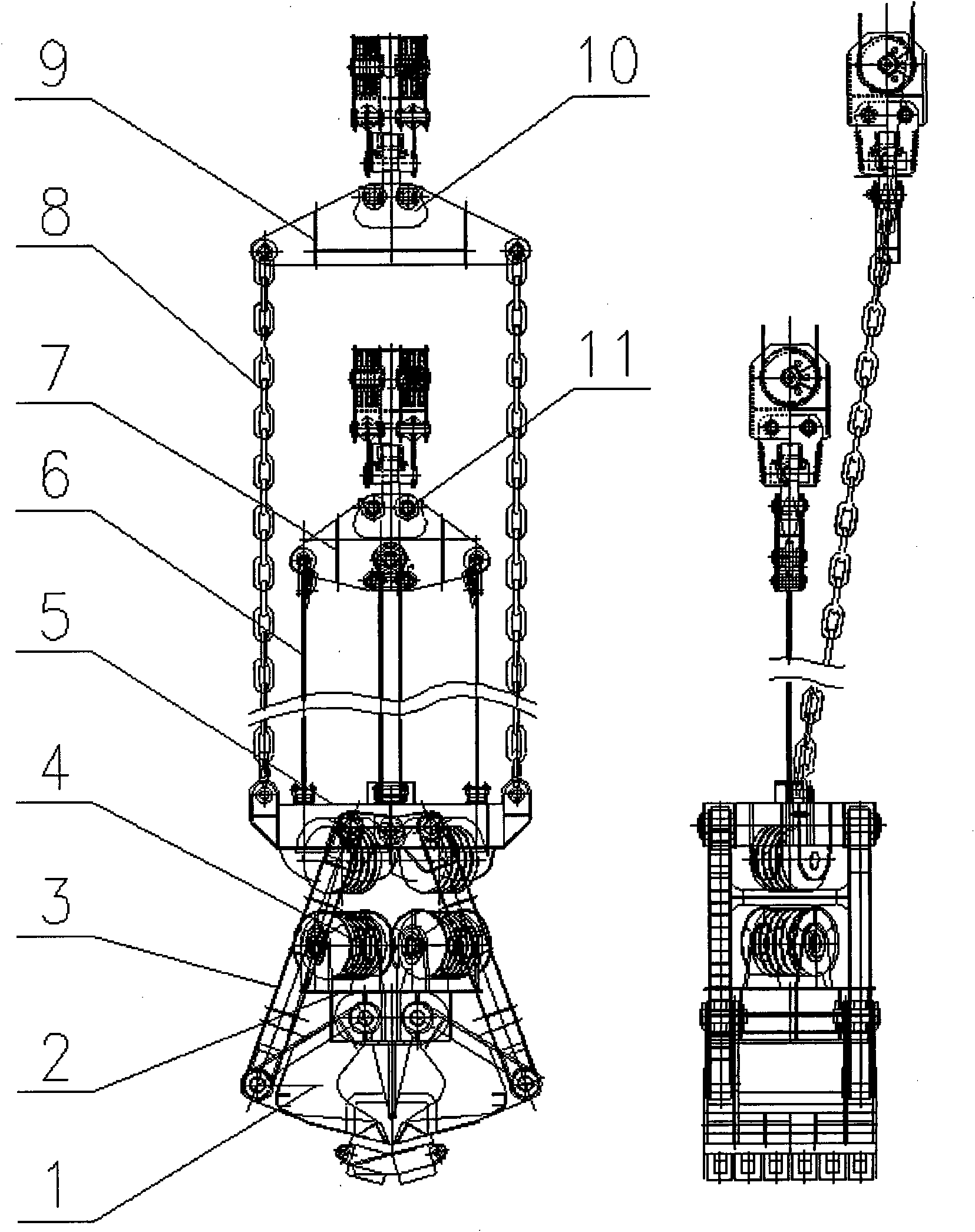
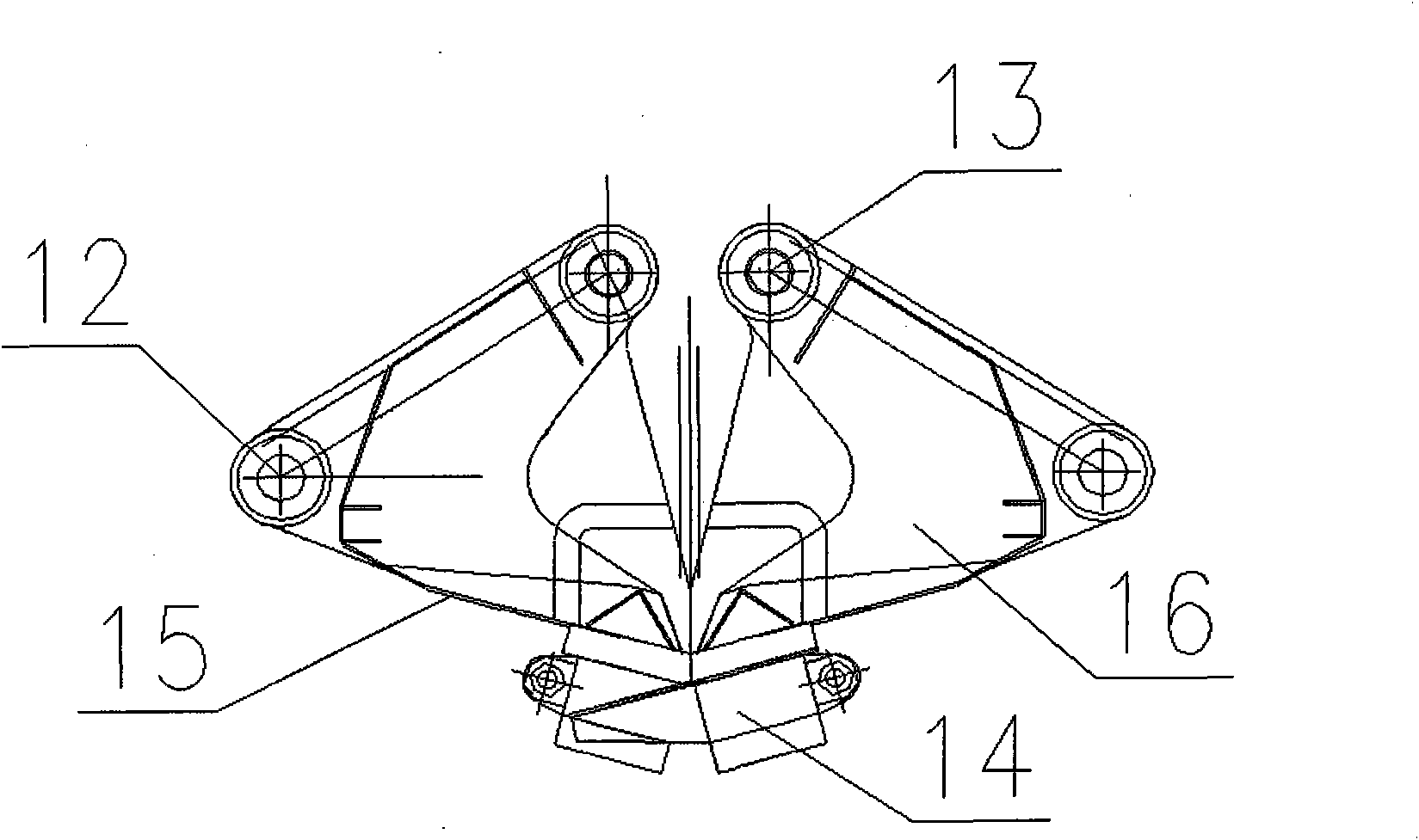
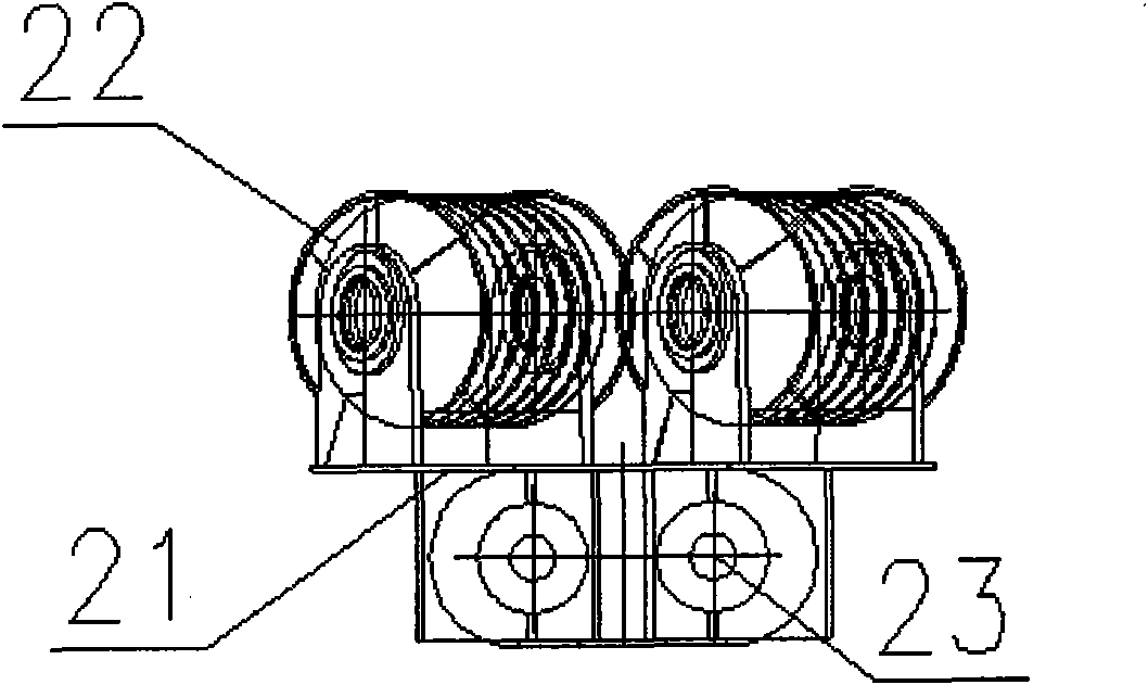
[0035] In order to make the technical means, creative features, goals and effects achieved by the present invention easy to understand, the present invention will be further described below in conjunction with specific illustrations. The 500-ton seabed salvage grab of the present invention comprises a grab bucket body, a strut, a grab middle beam, a grab head, a balance beam, a pulley block system, and steel wire ropes and supporting steel cables, such as figure 1As shown: the bucket body 1 of the grab is connected to the bucket teeth 14, the bucket body is connected to the grab head 5 through the support rod 2, and the other end of the bucket body is connected to the middle beam of the grab bucket, and the connection method is pin connection, and the grab The head of the bucket and the strut are used as the supporting structure of the main grab, which is relatively static. The middle beam of the grab is connected to the bucket body as a part of the direct grabbing action, and ...


PUM


Abstract

The invention discloses a giant undersea salvage grab bucket. The grab bucket comprises a grab bucket body, a grab bucket central beam, a grab bucket head part, grab bucket balance beams, a pulley block system, steel wire ropes and bearer cables, wherein the pulley block system improves the excavating force of the grab bucket by providing a magnifying power through wound steel wire ropes; and besides, high-intensity bucket teeth are arranged on the grab bucket body, so when the grab bucket is used for salvaging a sunken ship, the grab bucket body can dive to a sea floor in hundred meters, tear steel plates of the sunken ship by using a giant excavating force and then grab the sunken ship and salvage the sunken ship up. The giant undersea salvage grab bucket not only has basic functions of the conventional grab bucket, comprising a basic function of grabbing wares, but also has super high hoisting capacity and 500-ton grabbing capacity, and is particularly suitable for undersea sunken ship salvage. As the grab bucket has great excavating capacity and can tear steel plates of sunken ships, the efficiency of marine sunken ship salvage is greatly improved and the economic benefit of grab buckets is improved.

Description

Technical field: [0001] The invention relates to grab technology, in particular to the technical field of seabed salvage grab. Background technique: [0002] The grab is an important pick-up tool for grabbing goods. It is widely used in port loading and unloading operations, especially in the field of grabbing bulk cargo, such as coal loading and unloading, ore loading and unloading. At the same time, the grab is also an underwater Important operating tools such as salvage and channel dredging. The existing grabs are divided into loading and unloading grabs and salvage or dredging grabs according to their uses. The loading and unloading grabs have a small lifting capacity: generally between 5 and 80 tons; the dredging grabs have a small lifting capacity. It is mainly used to clean up channel silt; while the lifting capacity of the salvage grab is relatively large, because the lifting capacity of the salvage grab directly determines the salvage capacity of the modified grab;...

Claims


Application Information

Patent Timeline
Patent Type & Authority Applications(China)
IPC IPC(8): B63C7/20
Inventor 王悦民陈自强余智雄江杭生沈莹童民慧张玉芹仝瑞国高翔
Owner SHANGHAI MARITIME UNIVERSITY
Learn More