


Quick Research
Generate reliable direction feasibility study reports for your R&D in just a few steps.

Technical Q&A
Discover and master advanced knowledge NOW. Basics, ideas, possibilities, all at once.

Find Solutions
As an expert in R&D theories, this can generate solutions to your technical problems instantly.

Evaluate Feasibility
Analyze your overall solution with one click, know your potential R&D risks in advance.

Monitor Landscape
Get weekly tech updates, stay abreast of the latest tech innovations and key insights.
Production method, device and network equipment of binding table
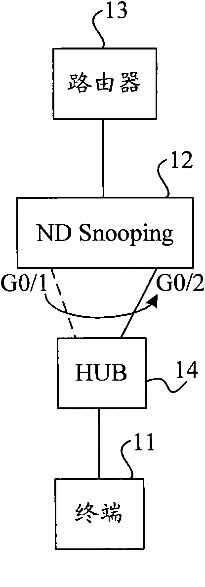
A technology for generating a device and a binding table, which is applied in the field of network communication and can solve the problems that terminals 11 cannot communicate normally and cannot sense
- Summary
- Abstract
- Description
- Claims
- Application Information
AI Technical Summary
Problems solved by technology
Method used
Image


Examples
Embodiment 1
[0023] image 3 It is a flowchart of a method for generating a binding entry provided in Embodiment 1 of the present invention. The execution subject of this embodiment is a device for generating binding entries, such as image 3 As shown, the method for generating a binding entry in this embodiment includes:
[0024] Step 301, monitor the local MAC address table;
[0025] Wherein, the device for generating a binding entry in this embodiment may be independent of the network device and be connected to the network device, or may be set in the network device as a functional module of the network device. The network device may be, for example, an ND Snooping device or a routing device (such as a Layer 3 switch) with an ND Snooping function.
[0026] In this step 301, the device for generating binding entry entries monitors a local Medium Access Control (MAC) address table to find out whether network migration occurs in the network through changes in the MAC address table. For...
Embodiment 2
[0034] Figure 4 It is a flow chart of a method for generating a binding entry provided by Embodiment 2 of the present invention. This embodiment can be implemented based on Embodiment 1, and its execution subject is also a device for generating binding entries, such as figure 2 As shown, the method for generating a binding entry in this embodiment includes:
[0035] Step 401, monitor the local MAC address table;
[0036] Step 402, judging whether the monitored MAC address table has changed; when the binding entry generating device detects that the MAC address table has changed, execute step 403; otherwise, return to step 401, and continue to perform the monitoring operation.
[0037] Step 403, generate a detection message according to the change entry information in the MAC address table and the pre-stored RA message information, and execute step 404;
[0038] This step 403 is used for when the binding entry generation device detects that its MAC address table has changed...
Embodiment 3
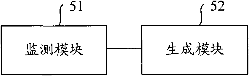
[0053] Figure 5 It is a schematic structural diagram of an apparatus for generating a binding entry provided by Embodiment 3 of the present invention. The binding entry generation device in this embodiment can be connected to the network equipment independently of the network equipment, or can be set in the network equipment as a part of the network equipment, and is mainly used to generate binding entries and perform data processing on the data sent by the terminal. Source address security filtering. Wherein, the network device may be an independent ND Snooping device, or a routing device (for example, a layer-3 switch) capable of ND Snooping. like Figure 5 As shown, the device for generating a binding entry in this embodiment includes: a monitoring module 51 and a generating module 52 .
[0054] Wherein, the monitoring module 51 is connected with the generating module 52, and is used for monitoring the MAC address table of the local binding entry generating device. Spe...
PUM
 Abstract
Description
Claims
Application Information
 - R&D Engineer
- R&D Manager
- IP Professional
- Industry Leading Data Capabilities
- Powerful AI technology
- Patent DNA Extraction
Browse by: Latest US Patents, China's latest patents, Technical Efficacy Thesaurus, Application Domain, Technology Topic, Popular Technical Reports.
© 2024 PatSnap. All rights reserved.Legal|Privacy policy|Modern Slavery Act Transparency Statement|Sitemap|About US| Contact US: help@patsnap.com