Electric loading mechanism with adjustable counterweight

A loading mechanism and electric technology, applied in the direction of mechanically driven excavators/dredgers, etc., can solve the problems of poor starting, complex hydraulic system, weak work, etc. The effect of efficiency

Inactive Publication Date: 2012-05-02
GUANGXI UNIV
View PDF0 Cites 0 Cited by
  • Summary
  • Abstract
  • Description
  • Claims
  • Application Information

AI Technical Summary

Problems solved by technology

However, the hydraulic loader uses hydraulic oil as the medium for power transmission. Its start-up is poor, and it is easy to leak due to the wear of internal components, and there are many components involved. The leaked hydraulic oil will cause environmental pollution and overheating. , inability to work, etc.
With the increase of the functions of the loader, its hydraulic system becomes more and more complex, causing its failure to appear more suddenly and concealed

Method used


Image

  • Electric loading mechanism with adjustable counterweight
  • Electric loading mechanism with adjustable counterweight
  • Electric loading mechanism with adjustable counterweight

Examples


Embodiment Construction

[0020] The technical solutions of the present invention will be further described below in conjunction with the accompanying drawings and embodiments.

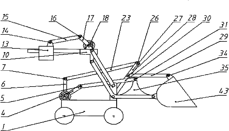
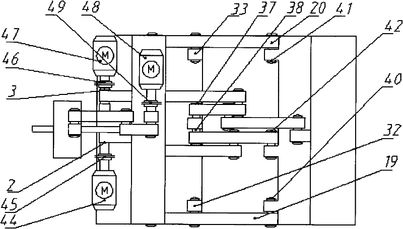
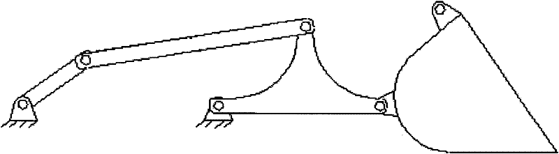
[0021] control figure 1 , figure 2 and image 3 , the bucket lifting mechanism is composed of the first active rod 4, the first connecting rod 30, the second connecting rod 35 and the bucket 43, as figure 1 shown. One end of the first active rod 4 is connected with the first shaft coupling 45 and the first servo motor 44 through the first reaming hole 2, and the first servo motor 44 is installed on the car body 1, such as figure 2 As shown, the other end is connected with the first connecting rod 30 through the second hinged hole 5; the other end of the first connecting rod 30 is connected with the second connecting rod 35 through the third hinged hole 31, as figure 1 As shown; the other two ends of the second connecting rod 35 are respectively connected with the car body 1 and the bucket 43 through the fourth reaming ho...


PUM


Abstract

The invention relates to an electric loading mechanism with an adjustable counterweight, comprising a bucket lifting mechanism, a bucket turning mechanism, a counterweight adjusting mechanism and a bucket. A loader is driven by three servo motors, wherein the first servo motor is used for controlling the bucket lifting mechanism, the second servo motor is used for controlling the bucket turning mechanism, and the third servo motor is used for controlling the counterweight adjusting mechanism. When the electric loading mechanism works, the included angle between the bucket and the ground is unchanged when the bucket is lifted, and the included angle between the counterweight and the ground is unchanged when the counterweight falls off. The electric loading mechanism can solve the problems of high requirement of spare parts, short service life, oil leakage, and the like of the traditional hydraulic loader.

Description

technical field [0001] The invention relates to the field of mechanical engineering, in particular to an electric loading mechanism with adjustable counterweight. Background technique [0002] Loader is an important construction machinery, which is widely used in the earthwork construction of highways, railways, construction, hydropower, ports, mines and other construction projects. Most of the existing loaders rely on hydraulic transmission to realize the loading and unloading action, which has the advantages of flexible action, stable work, simple and compact structure, etc. However, the hydraulic loader uses hydraulic oil as the medium for power transmission. Its start-up is poor, and it is easy to leak due to the wear of internal components, and there are many components involved. The leaked hydraulic oil will cause environmental pollution and overheating. , Inability to work and so on. With the increase of the functions of the loader, its hydraulic system becomes more...

Claims


Application Information

Patent Timeline
Patent Type & Authority Patents(China)
IPC IPC(8): E02F3/42E02F3/36
Inventor 蔡敢为王红州潘宇晨温芳谢红梅张转徐细勇吴笃超
Owner GUANGXI UNIV
Why Eureka
Try Eureka