Wire winding method and wire winding machine

A winding method and winding machine technology, applied in coil manufacturing, inductance/transformer/magnet manufacturing, electrical components, etc.

Inactive Publication Date: 2010-12-01
NIPPON SERBIG
View PDF8 Cites 13 Cited by
  • Summary
  • Abstract
  • Description
  • Claims
  • Application Information

AI Technical Summary

Problems solved by technology

However, regardless of whether electrical synchronization or mechanical synchronization is used, adjusting the rotation angle or maintaining the rotation angle requires corresponding skills and man-hours

Method used


Image

  • Wire winding method and wire winding machine
  • Wire winding method and wire winding machine
  • Wire winding method and wire winding machine

Examples


Embodiment Construction

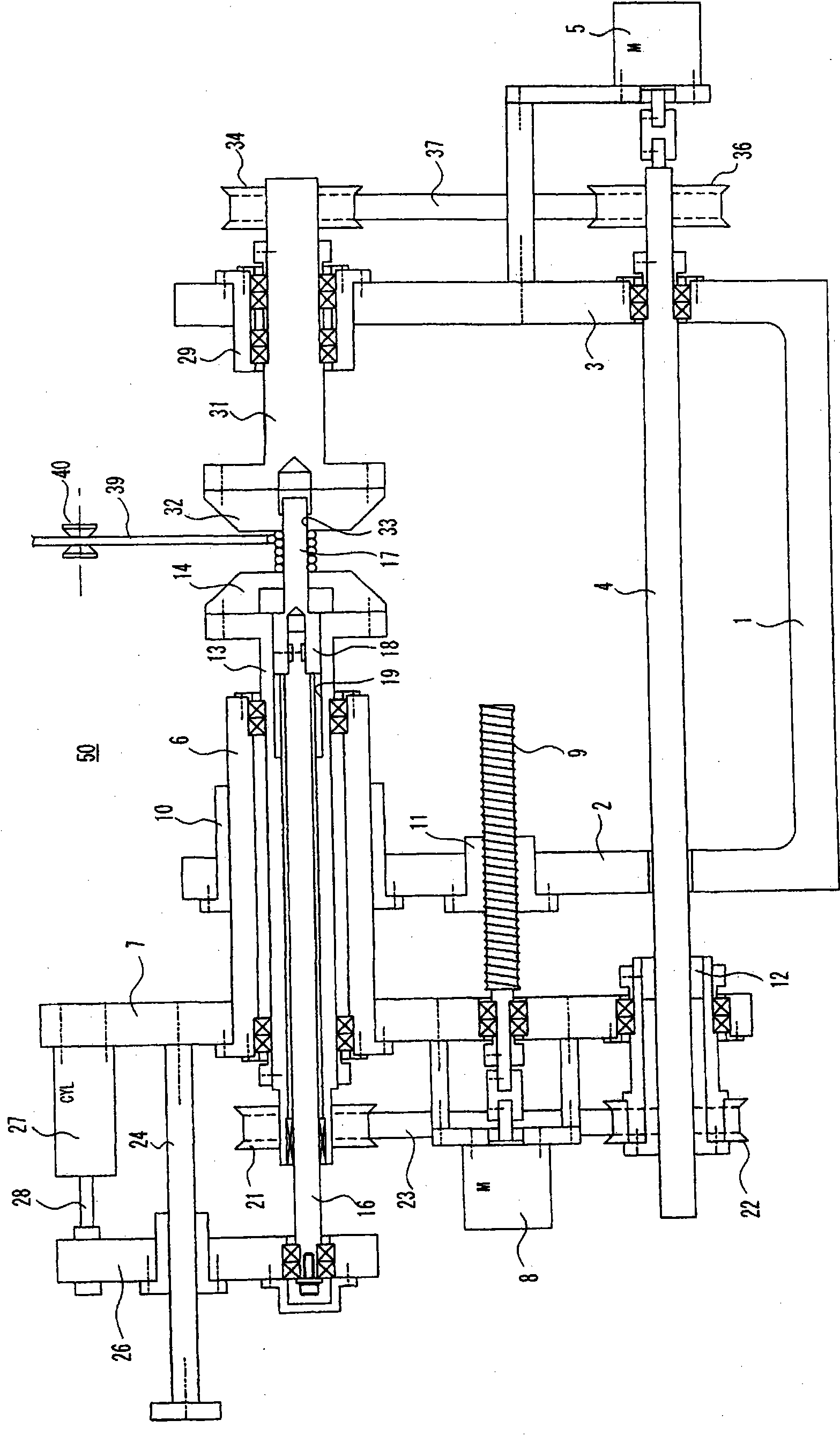
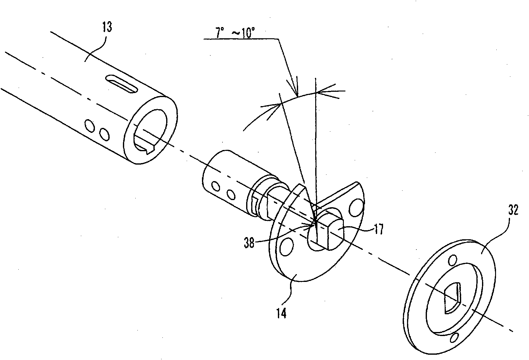
[0121] Hereinafter, the present invention will be described in detail based on the drawings and examples. figure 1 It shows the front of the winding machine 50 in an Example. In principle, each part is shown in section, but hatching is not used because it is difficult to see clearly. Figure 3 ~ Figure 6 the same. figure 2 The movable-side reel 14, the fixed-side reel 32, the winding mandrel 17, and the like are shown. about the figure 2 , are only marked with symbols, and their descriptions are omitted. In addition, regarding the structure of the winding machine, centering on the above-mentioned publications, Japanese Patent Application Laid-Open No. 2005-116657, Japanese Patent Publication No. 2001-358029, Japanese Patent Publication No. Hei 10-304628, etc. It is well known. Therefore, only the parts considered necessary for the description of the embodiment will be described here.

[0122] figure 1 Among them, 1 is the base, and the left side of the main body 2 a...


PUM


Abstract

Provided are a wire winding method and a wire winding machine, in which aligning performance of particularly the first layer, a positional stability of a cross-point, and so on can be maintained in the progress of thinning of a wire, decreasing of the diameter of a winding core, diversifying of the sectional surface of a winding core and so on, whereby the wire can be wound at a higher speed and a preparation time is not required to take so much for alteration of a product. During a period from the start of winding of the first layer up to the completion of the winding, a fixation side winding frame (32), a wire guide (40) and a tension device (not shown in the figures) are set to remain unchanged in position relationship. During the same period up to the completion of the first layer winding, a winding core (17) and a movable side frame (14) are intermittently separated by every predetermined amount with respect to the fixation side winding frame (32). By such a separation, a predetermined gap (G) compatible with an outer diameter of a wire (39) is maintained between the wire (39) already wound and the fixation side winding frame (32) at a position where a new wire (39) is then wound. Under these conditions, the wire supplied from the tension device enters into the maintained gap and is successively wound around the winding core (17), whereby the first layer winding is carried out.

Description

technical field [0001] The invention relates to a winding method and a winding machine, in particular to a winding method and a winding machine suitable for winding small hollow coils using thin wires. Background technique [0002] Along with the miniaturization of electronic equipment, the miniaturization of air core coils is also advancing. Accordingly, wire rods (metal wires) that are raw materials are being thinned year by year. Smaller diameters of winding mandrels and diversification of cross-sectional shapes are also advancing. Accordingly, maintaining the orderliness of the first layer of coils becomes more and more important. Because if the neatness is poor, it will easily cause chaotic lines after the second layer. Here, the so-called diversification of cross-sectional shape does not mean that the cross-section of the winding mandrel is circular or slightly elliptical, but refers to an ellipse with a higher ellipticity, a rectangle or a polygon with a shorter sh...

Claims


Application Information

Patent Timeline
Patent Type & Authority Applications(China)
IPC IPC(8): H01F41/06B65H54/28
CPCH01F41/0633B65H54/2848B65H75/241H01F41/082
Inventor 佐佐木幸喜
Owner NIPPON SERBIG
Why Eureka
Try Eureka