Pedal washing machine
A washing machine and foot-operated technology, applied in the field of washing machines, can solve the problems of high maintenance rate, easy damage, complex structure, etc., and achieve the effects of zero consumption, saving production and installation costs, and simplifying the clutch transmission structure
- Summary
- Abstract
- Description
- Claims
- Application Information
AI Technical Summary
Problems solved by technology
Method used
Image
Examples
Embodiment 1
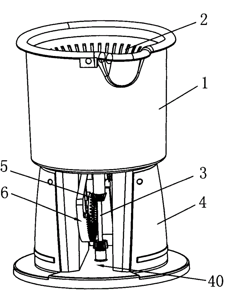
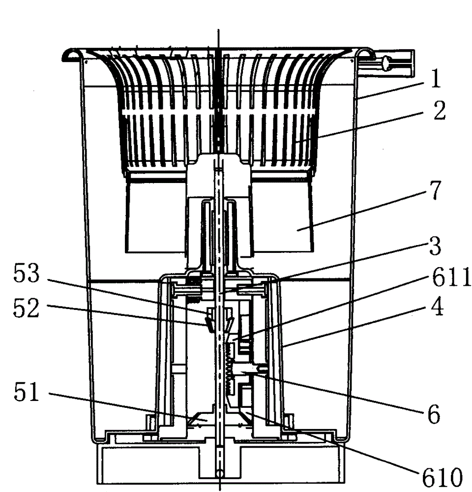
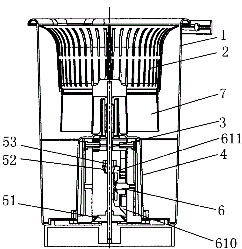
[0036] Such as Figure 4As shown, the pedal device 6 described in this embodiment includes an arc-shaped plate 61, a pedal 62 integrated with the arc-shaped plate 61 and extending outward along its radius, and a reset torsion spring 63. The base 4 is provided with a For the opening in the vertical direction to the outside, the pivot of the arc-shaped plate 61 is erected in the opening 40. The center of rotation is the center of the arc-shaped plate. It can rotate back and forth in the direction of the opening by relying on the foot pedal and the torsion spring reset, similar to swinging, the foot pedal The plate 62 extends from the opening to the outside of the base 4; the arc plate 61 is provided with a second drive bevel 610 obliquely downward along the circumference, the second drive bevel 610 can mesh with the washing bevel 51, and on the arc plate 61 Between the circumference and the center of the circle, a first driving bevel gear 611 is arranged obliquely upward paralle...
Embodiment 2
[0040] Such as Figure 5 As shown, the pedal device 6 described in this embodiment includes an arc-shaped plate 61, a pedal 62 integrated with the arc-shaped plate 61 and extending outward along its radius, and a reset torsion spring. The base 4 is provided with a pair of outer The opening in the vertical direction, the arc-shaped plate is located in the opening, and can rotate back and forth in the direction of the opening by relying on the foot pedal and the torsion spring to reset, similar to swinging, the foot pedal 62 extends from the opening to the outside of the base 4, the above structure is consistent with Embodiment 1 is the same; the arc-shaped plate 61 is provided with a second driving bevel tooth 610 obliquely downward along the circumference, the second driving bevel tooth 610 can mesh with the washing bevel tooth 51, and the arc-shaped plate 61 is parallel to the circumference. There is an arc groove 64, and the arc groove 64 is provided with an inner rack 65 al...
Embodiment 3
[0043] Such as Figure 6 As shown, the pedal device 6 described in this embodiment includes an arc-shaped plate 61, a pedal 62 integrated with the arc-shaped plate 61 and extending outward along its radius, and a reset torsion spring. The base 4 is provided with a pair of outer The opening in the vertical direction, the arc-shaped plate is located in the opening, and can rotate back and forth in the direction of the opening by relying on the foot pedal and the torsion spring to reset, similar to swinging, the foot pedal 62 extends from the opening to the outside of the base 4, the above structure is consistent with The first embodiment is the same; the arc-shaped plate 61 has an arc-shaped groove 64 parallel to the circumference, and the arc-shaped groove 64 is provided with an inner rack 65 along the outer edge of the arc-shaped edge. The corresponding inner rack 65 pivots are provided with a pair of The double gear, the rotating shaft of the double gear passes through the ar...
PUM
 Abstract
Description
Claims
Application Information
 - R&D
- Intellectual Property
- Life Sciences
- Materials
- Tech Scout
- Unparalleled Data Quality
- Higher Quality Content
- 60% Fewer Hallucinations
Browse by: Latest US Patents, China's latest patents, Technical Efficacy Thesaurus, Application Domain, Technology Topic, Popular Technical Reports.
© 2025 PatSnap. All rights reserved.Legal|Privacy policy|Modern Slavery Act Transparency Statement|Sitemap|About US| Contact US: help@patsnap.com


