
Ing image display device

An image display device, a scanning type technology, which can be used in projection devices, image communication, optics, etc., and can solve problems such as driving difficulties.

Inactive Publication Date: 2010-11-24
PANASONIC CORP
View PDF2 Cites 40 Cited by
  • Summary
  • Abstract
  • Description
  • Claims
  • Application Information

AI Technical Summary

Problems solved by technology

However, for the reasons described above, it is difficult to drive to correct the shape of the scanning area or the interval between scanning lines.

Method used


Image

  • Ing image display device
  • Ing image display device
  • Ing image display device

Examples


Embodiment approach 1

[0039] Hereinafter, embodiments of the present invention will be described with reference to the drawings.

[0040] First, the arrangement relationship of each component of the scanning image display device according to the present embodiment and the shape of a scan pattern will be described.

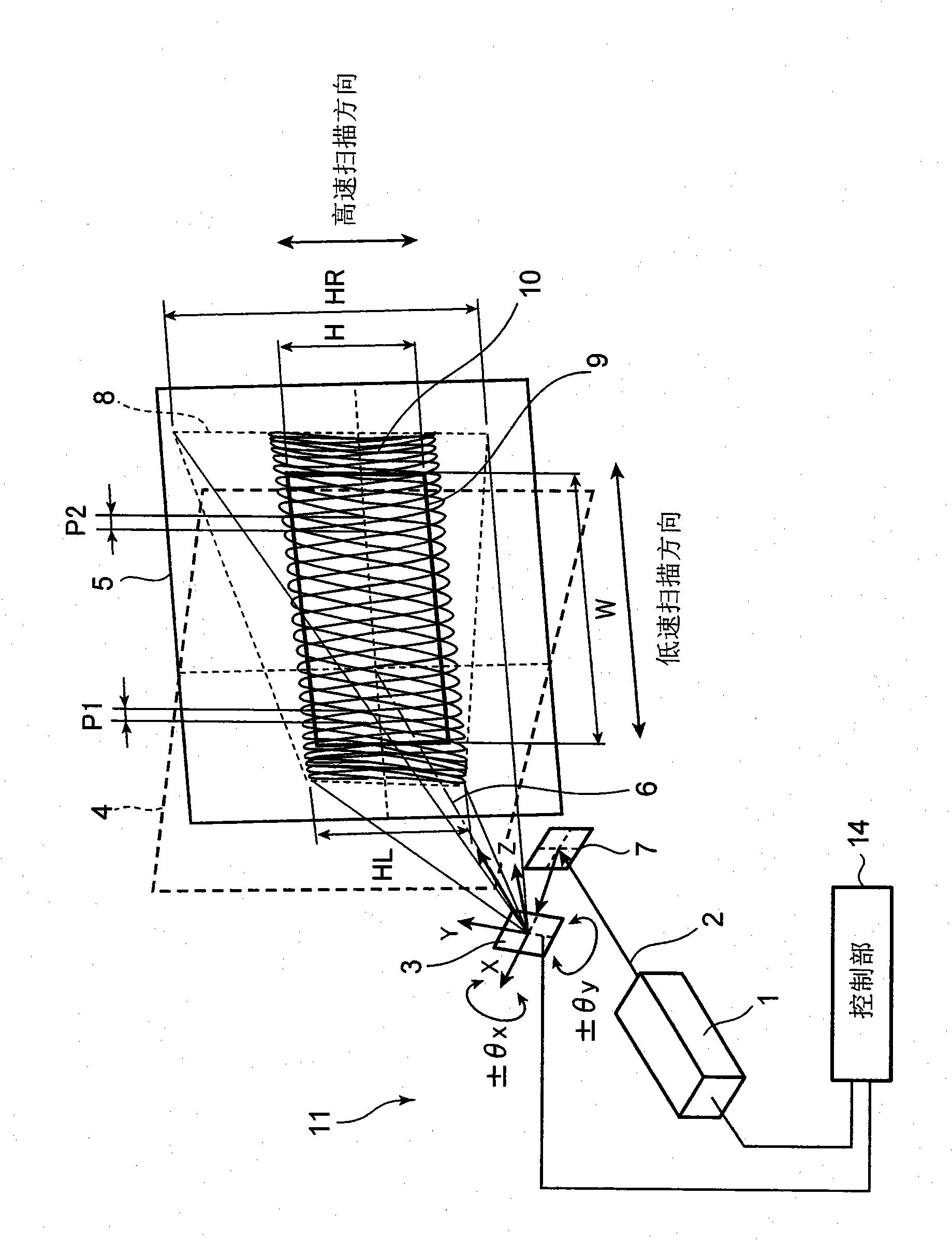
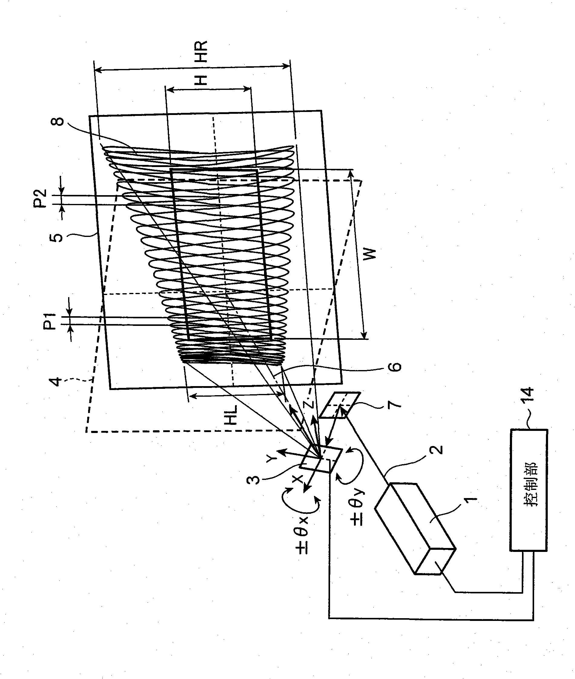
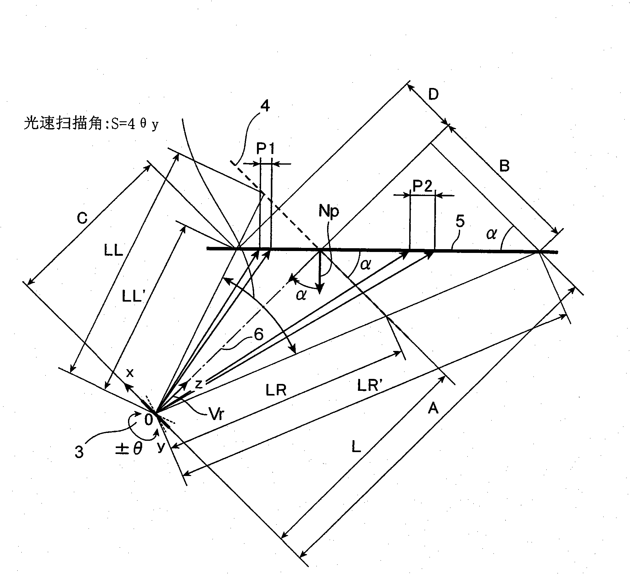
[0041] Figure 1 to Figure 3 A schematic configuration of the scanning image display device according to Embodiment 1 is shown. figure 1 It is a perspective view showing a scanning trajectory by the driving method according to this embodiment. figure 2 is expressed with figure 1 A perspective view of a scanning trajectory when a conventional driving method is applied to a scanning image display device having the same structure. image 3 yes means figure 1 A top view of the arrangement of the scanning mirror and the projection surface in the scanning image display device shown.

[0042] The scanning image display device 11 in this embodiment is such as figure 1 As shown, it in...

Embodiment approach 2

[0108] Next, an example in which the scanning image display device of the present invention is applied to a vehicle will be described.

[0109] Figure 7 It is a schematic diagram showing the arrangement of an in-vehicle scanning image display device according to Embodiment 2 of the present invention. Figure 7 It is a schematic diagram of a driver's seat of a vehicle seen from the rear, and a windshield 71 , a rearview mirror 72 , a steering wheel 73 , and the like are installed in the vehicle. The vehicle-mounted scanning image display device projects an instrument panel display 76 from a projection opening 74 in the center of the dashboard to a display area (projection surface) provided behind the steering wheel 73 . The instrument panel display 76 displays a speedometer, various indicators, and the like.

[0110] Furthermore, the in-vehicle scanning image display device also projects a driver's seat display 77 or a passenger's seat display 78 from the projection opening ...


PUM


Abstract

A scanning image display device comprises a light source unit for emitting a laser beam, a scanning mirror for two-dimensionally scanning the laser beam in a first direction and a second direction intersecting the first direction, and a control unit for controlling the driving of the scanning mirror, wherein the control unit drives the scanning mirror in such a manner that the scanning frequency in the first direction is higher than the scanning frequency in the second direction, and changes the scanning amplitude in the first direction by changing the scanning frequency in the first direction in synchronization with the cycle of the scanning frequency in the second direction.

Description

technical field [0001] The present invention relates to a scanning image display device such as an HMD (Head Mounted Display, head-mounted display) that uses a scanning mirror to scan a laser beam. Background technique [0002] Conventionally, various methods have been proposed for image display devices such as HMDs (Head Mounted Displays) worn on the user's head to display images. , Two-dimensional scanning of the laser beam and the way of direct imaging on the retina of the eye, etc. [0003] Such an image display device is required to be compact and lightweight as a whole in order to reduce the wearing burden of the user and enable long-term use. Furthermore, if the image display device is configured with a design equivalent to that of commonly used spectacles, it can be worn all the time like normal spectacles for activities. [0004] However, in order to achieve higher image quality and wider viewing angles, the method of using a pixel-type display device uses a displ...

Claims


Application Information

Patent Timeline
Patent Type & Authority Applications(China)
IPC IPC(8): G02B26/10G02B17/08G02B25/00G02B27/01G02B27/02G03B21/00
CPCG02B26/108G02B27/0101G02B26/101G02B27/0172G03B21/00G03B21/006H04N9/3129
Inventor 黑冢章
Owner PANASONIC CORP
Learn More