
Control method of voltage fluctuation feedback of grid-connected current transformer under asymmetric voltage

A voltage fluctuation and feedback control technology, applied in the field of feedback control, can solve the problems of real-time system threat, complex control process implementation, and large amount of calculation, and achieve the effects of easy implementation, reduced output current distortion, and small amount of calculation.

Active Publication Date: 2013-04-10
STATE GRID ELECTRIC POWER RES INST
View PDF0 Cites 0 Cited by
  • Summary
  • Abstract
  • Description
  • Claims
  • Application Information

AI Technical Summary

Problems solved by technology

But they all need to decompose the positive and negative sequence components of voltage and current. At the same time, the control process is complex and the calculation is large, which is a potential threat to real-time systems.

Method used


Image

  • Control method of voltage fluctuation feedback of grid-connected current transformer under asymmetric voltage
  • Control method of voltage fluctuation feedback of grid-connected current transformer under asymmetric voltage
  • Control method of voltage fluctuation feedback of grid-connected current transformer under asymmetric voltage

Examples


Embodiment Construction

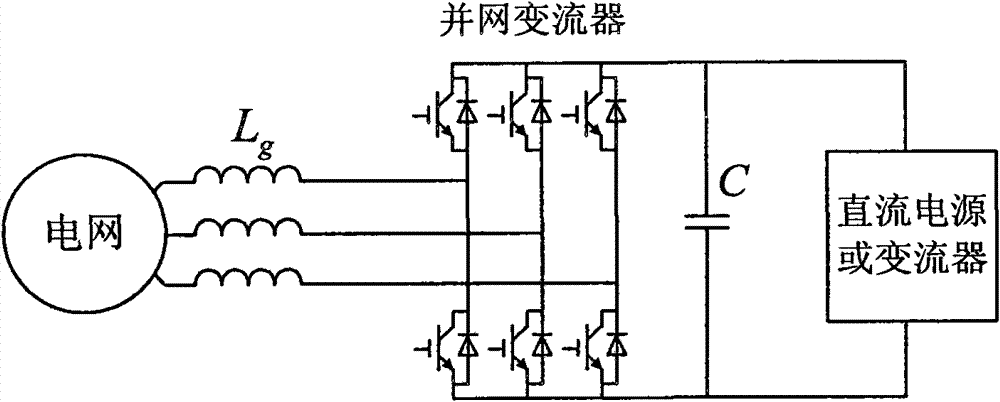
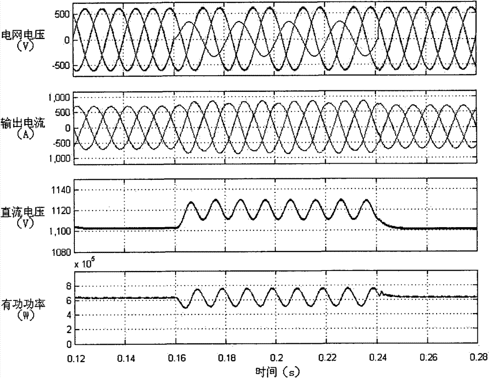
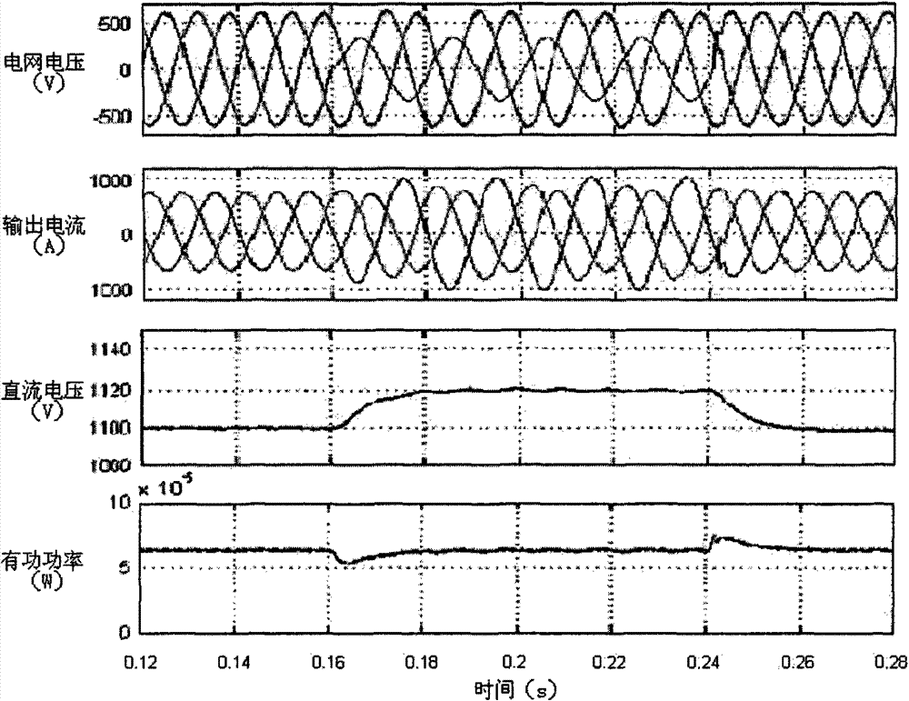
[0030] The voltage fluctuation feedback control method adopts the control method of the voltage outer loop and the current inner loop, and its realization block diagram is shown in the attached Figure 4 shown. The control first needs to detect various electric quantities, including DC voltage, grid voltage and three-phase current.

[0031] The DC voltage u can be measured by using the Hall element dc .

[0032] Use the voltage transformer PT (Potential Transformer) to measure the voltage of the three-phase grid, orientate the A-phase voltage, and perform d-q transformation to obtain the voltage d-axis component u d , q-axis component u q and the voltage phase angle θ + . When the grid voltage contains negative sequence components, it can be expressed as

[0033]

[0034] In the formula, the subscripts "d" and "q" represent the d-axis component and the q-axis component respectively, the subscripts "+" and "-" represent the positive sequence component and negative sequ...


PUM


Abstract

The invention relates to a control method of a grid-connected current transformer under asymmetric voltage, which comprises the following steps of: detecting direct current voltage udc by using a Hall element, detecting grid voltage by using a PT (Potential Transformer) and converting the grid voltage to a d-q coordinate system to acquire a d-axis component ud and a q-axis component uq; multiplying the output of direct current voltage closed loop by coefficients to be respectively used as first components in a d-axis given value and a q-axis given value of the current; respectively extractingthe sum of duple work frequency fluctuation in the d-axis component ud and the q-axis component of the voltage, multiplying the voltage by a conversion coefficient of the current to be used as secondcomponents in the d-axis given value and the q-axis given value of the current; acquiring the d-axis given value and the q-axis given value of the current by adding two components to detect actual currents id and iq to form a current closed loop; and controlling the work of the current transformer through PWM modulation. The invention can maintain the active power of the current transformer to bestable under the condition of asymmetric grid voltage, inhibit the fluctuation of direct current-side voltage and reduce the distortion of the output current.

Description

technical field [0001] The invention relates to a feedback control method, in particular to a voltage fluctuation feedback control method of a grid-connected converter under asymmetrical voltage. Background technique [0002] In recent years, with the rapid development of power electronic devices, their application occasions have gradually increased and their application scope has gradually expanded, especially converters based on power electronic switches have been widely used. In motor control, energy conversion and other occasions, the application of converters makes the control more convenient and flexible. However, the traditional control method of the grid-connected converter is based on the premise of three-phase symmetrical grid voltage, which is sensitive to voltage changes, which makes it unable to adapt to the operating conditions of grid voltage asymmetry. In the case of long-line power transmission or asymmetrical faults in the power grid, voltage asymmetry occ...

Claims


Application Information

Patent Timeline
Patent Type & Authority Patents(China)
IPC IPC(8): H02J3/38H02M1/14
Inventor 赵紫龙吴维宁王伟石磊
Owner STATE GRID ELECTRIC POWER RES INST
Learn More