
Telescoping tube system for vacuum cleaner

A pipe system and vacuum cleaner technology, applied in the field of pipe systems, can solve the problems of reduced suction force, uneven flow, etc., and achieve the effects of improved suction efficiency, uniform flow profile, and reliable insulation

Active Publication Date: 2010-11-24
FISCHER ROHRTECHN
View PDF1 Cites 4 Cited by
  • Summary
  • Abstract
  • Description
  • Claims
  • Application Information

AI Technical Summary

Problems solved by technology

A disadvantage of this pipe system known from the prior art is that the suction channel has a plurality of openings and connection points through which secondary air can enter the pipe system, so that, for example, when using the pipe system as a vacuum cleaner pipe The suction force is reduced due to the (to) suction of the secondary air
In addition, the cable channel causes turbulence in the suction channel and thus an inhomogeneous flow

Method used


Image

  • Telescoping tube system for vacuum cleaner
  • Telescoping tube system for vacuum cleaner
  • Telescoping tube system for vacuum cleaner

Examples


Embodiment Construction

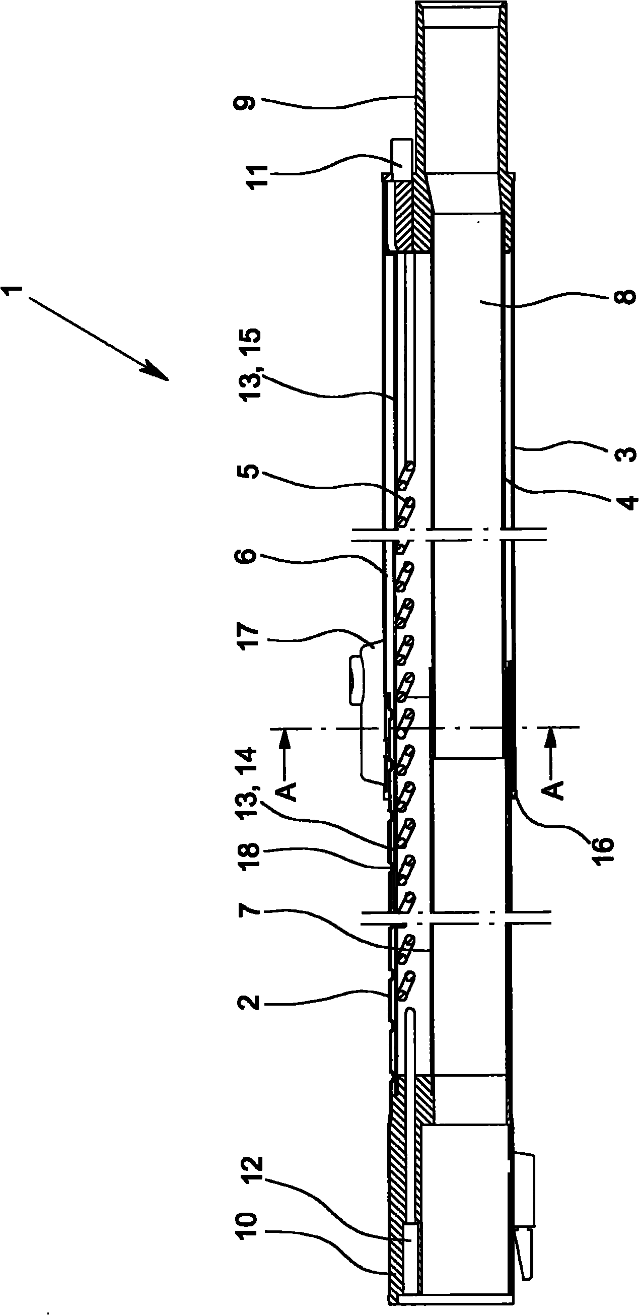
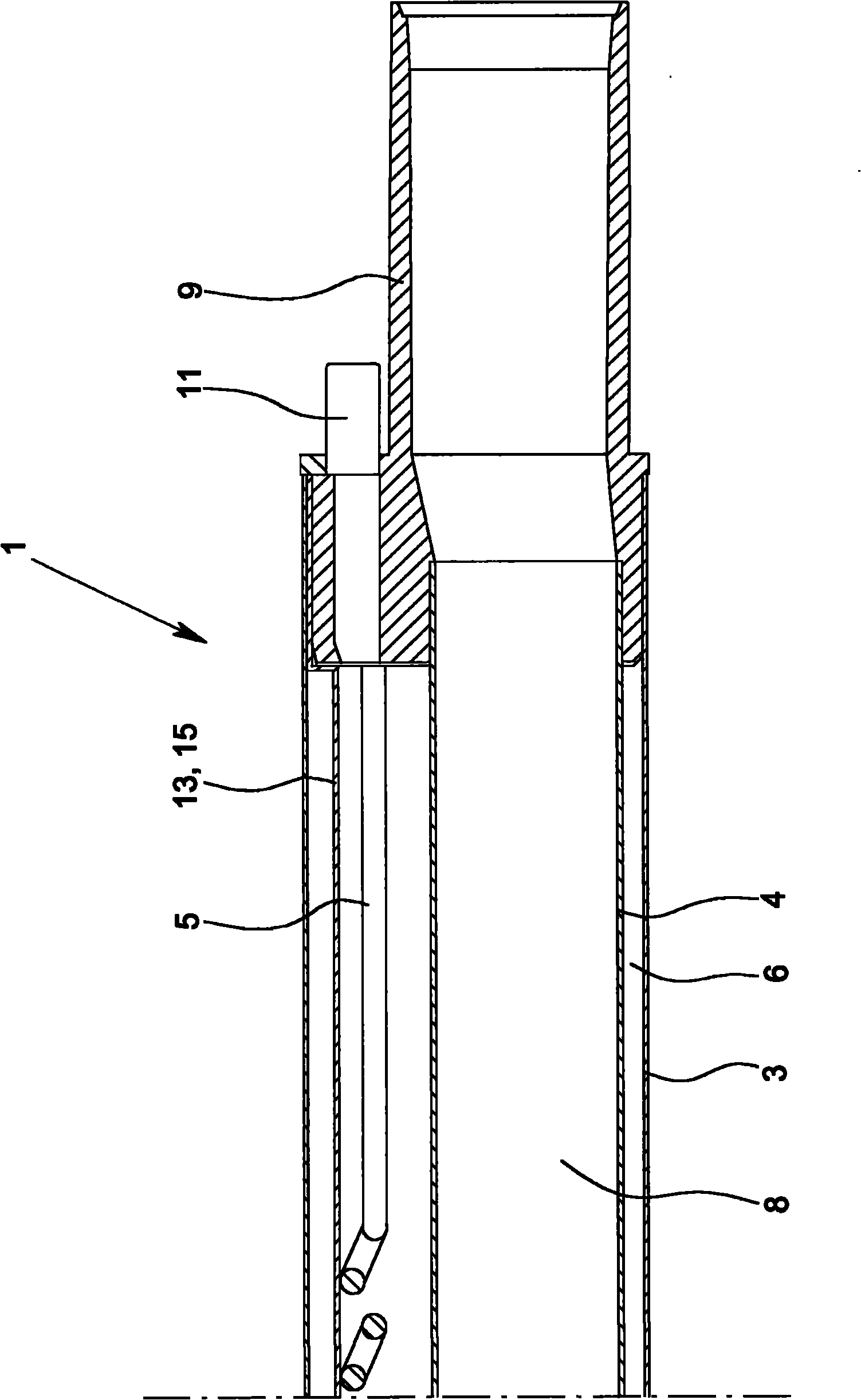
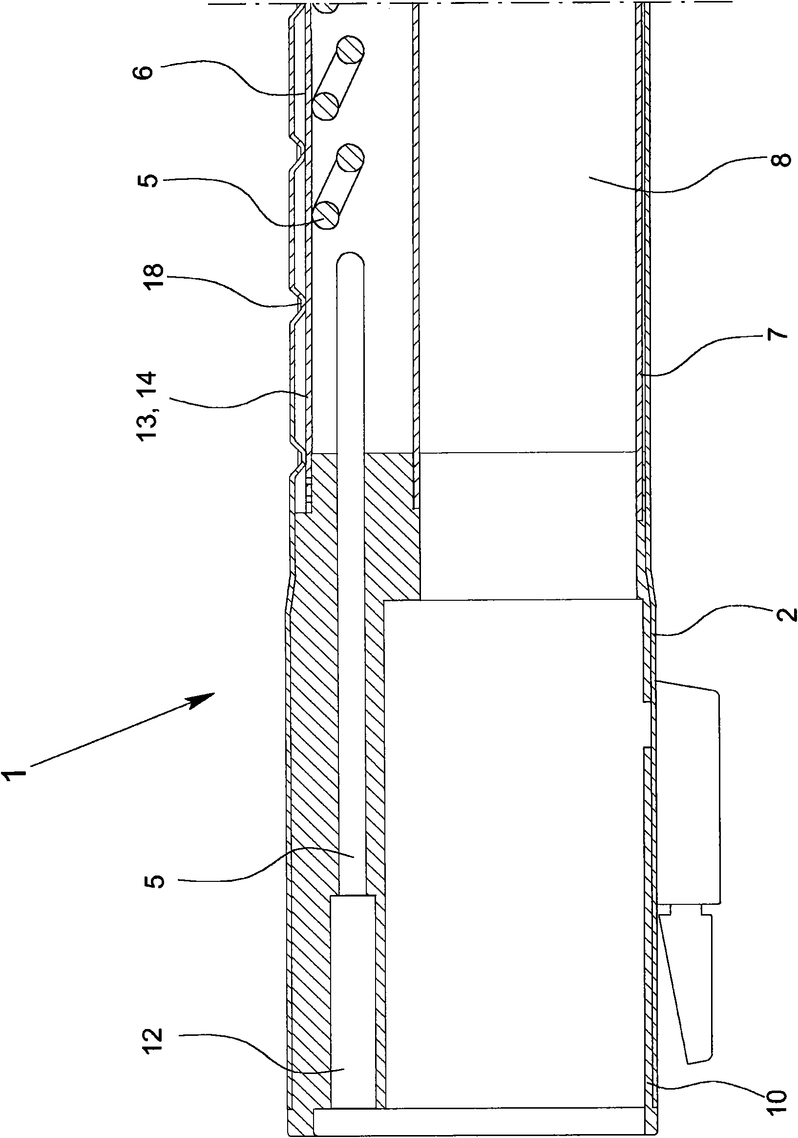
[0028] figure 1 A telescoping pipe system 1 for a vacuum cleaner is shown, which has an inner housing pipe 2 , an outer housing pipe 3 , an inner suction pipe 4 and a cable 5 . The inner shell tube 2 has a smaller cross-section than the outer shell tube 3 , so the inner shell tube 2 and the outer shell tube 3 form a telescopic shell channel 6 . The housing channel 6 surrounds the suction inner tube 4 and the cable 5 , wherein the cable 5 is guided inside the housing channel 6 and outside the suction inner tube 4 . The suction inner tube 4 together with the suction outer tube 7 forms a substantially closed suction channel 8 . The suction channel 8 extends inside the housing channel 6 and is arranged eccentrically in the housing channel 6 .

[0029] Both the housing channel 6 and the suction channel 8 are scalable in their length, since the outer housing tube 3 is movable relative to the inner housing tube 2 and the outer suction tube 7 is movable relative to the inner suction...


PUM


Abstract

A telescoping tube system (1) for a vacuum cleaner, with an inner jacket tube (2), an outer jacket tube (3), an inner suction tube (4) and a cable (5), the inner jacket tube (2) having a smaller cross section than the outer jacket tube (3) so that the inner jacket tube (2) and the outer jacket tube (3) form a telescoping jacket channel (6), the inner suction tube (4) being located inside of the jacket channel (6), and the cable (5) being guided within the jacket channel (6) and outside of the inner suction tube (4). In the telescoping tube system (1), losses of suction force by the intake of secondary air are reduced to a minimum and reliable cable routing is ensured by there being an outer suction tube, the outer suction tube (7) and the inner suction tube (4) forming an essentially closed suction channel (8) within the jacket channel (6).

Description

technical field [0001] The invention relates to a telescopic tube system for a vacuum cleaner with an inner housing tube, an outer housing tube, an inner suction tube and a cable, wherein the inner housing tube has a smaller cross-section than the outer housing tube, whereby The inner housing tube and the outer housing tube form a telescoping housing channel in which the suction inner tube is arranged and in which the cable can be guided within the housing channel and outside the inner suction tube. Background technique [0002] Telescopic tube systems are known in the prior art, in which the cable is guided along by means of a closed cable channel in the suction channel. Both the suction channel and the cable channel are telescopic and connected to one another in such a way that they always have essentially the same length. The cable channel completely surrounds the cable and protects this (cable) from contamination and damage from particles introduced through the suction ...

Claims


Application Information

Patent Timeline
Patent Type & Authority Applications(China)
IPC IPC(8): A47L9/24
CPCA47L9/246A47L9/244
Inventor M·科德斯S·科德斯
Owner FISCHER ROHRTECHN
Learn More