
Prosthesis shaft and system comprising a prosthesis shaft and prosthesis device

A technology of prosthesis and structure, applied in the field of system composed of prosthesis tube and prosthesis device

Active Publication Date: 2015-02-04
OTTO BOCK HEALTHCARE IP GMBH & CO KG
View PDF10 Cites 0 Cited by
  • Summary
  • Abstract
  • Description
  • Claims
  • Application Information

AI Technical Summary

Problems solved by technology

In addition, the amputation stump has large volume fluctuations, so the prosthetic tube may have difficulty fitting the amputation stump correctly
Additionally, patients often lack the ability to actively cooperate when fitting the prosthetic cartridge

Method used


Image

  • Prosthesis shaft and system comprising a prosthesis shaft and prosthesis device
  • Prosthesis shaft and system comprising a prosthesis shaft and prosthesis device
  • Prosthesis shaft and system comprising a prosthesis shaft and prosthesis device

Examples


Embodiment Construction

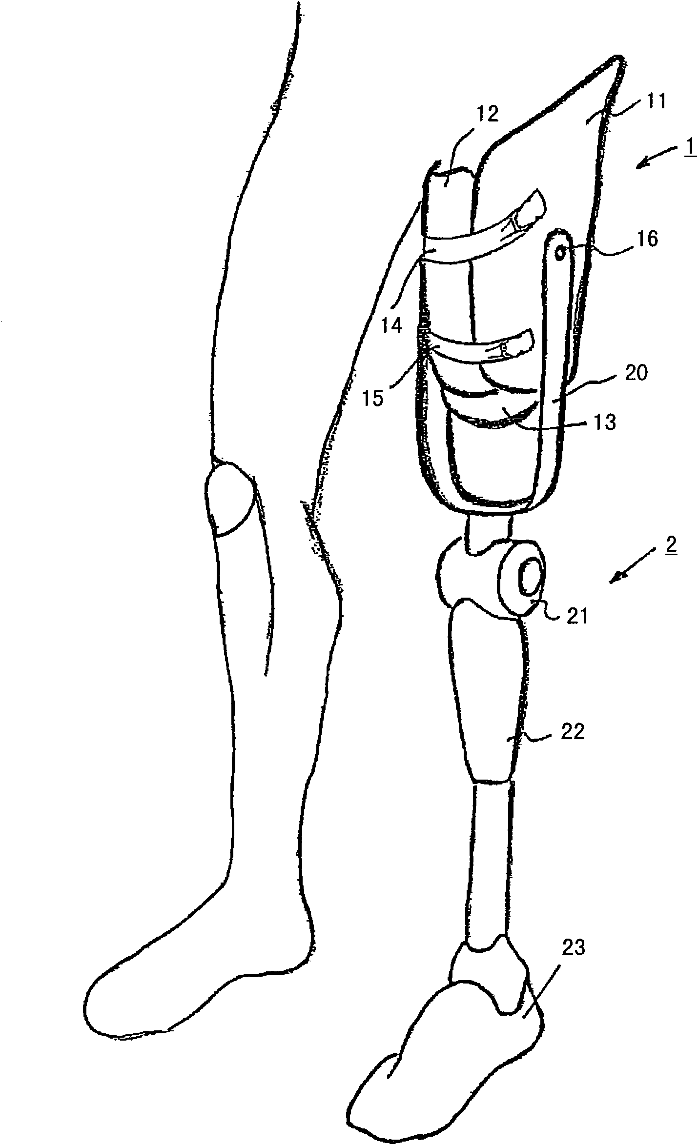
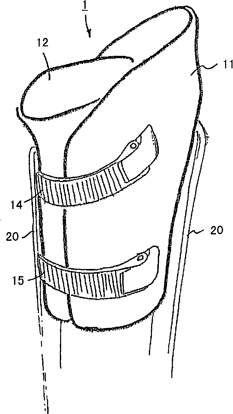
[0036] The two partial shells 11 , 12 are made of flat, dimensionally stable plastic and have a curvature so that it rests on the amputation stump or lining over the largest possible area. In the embodiment shown, the central part shell 12 is covered from the outside in the front region by the side part shells 11 . A corresponding covering can also take place at the rear, which means that the radius of curvature of the side part shells 11 is greater than the radius of curvature of the central part shell 12 . The separate partial shells 11 , 12 have an open cross section and, in the worn state, form a multi-part sleeve which is open both proximally and distally. The distal end of the prosthesis cartridge 1 is now closed by a cover 13 fastened to the partial shells 11 , 12 . The cover 13 serves to protect the distal end of the amputation stump. In principle, it is also possible for the cover 13 to be fastened or formed on the bushing.

[0037] On the partial shells 11 , 12 , ...


PUM


Abstract

The invention relates to a prosthesis shaft for receiving an amputation stump of an extremity, comprising connecting means for a distal prosthesis device (2), wherein the prosthesis shaft (1) comprises at least one shell (11, 12), which has an arched, open cross-section and the shell ends of which in the applied state overlap each other at least partially, at least one tensioning means (14, 15) being disposed on the shell (11, 12), said means acting in the circumferential direction and tensioning the shell ends relative to each other, and the shell (11, 12) being made of a dimensionally stable plastic having regions with varying elasticity.

Description

technical field [0001] The invention relates to a prosthetic cartridge for receiving amputated stumps of a limb, said prosthetic cartridge having connection means for a distal prosthetic device, and a system consisting of a prosthetic cartridge and a prosthetic device . Background technique [0002] Various methods and concepts are known from the prior art for providing artificial limbs to patients with (eg lower limb) amputations. For patients with thigh or lower leg amputations, or for patients with a severed knee, the traditional method of manufacturing a prosthetic cylinder is the plaster cast method, in which a plaster cast of the amputated stump is obtained from the patient, the plaster cast The model is used as a template for the stump model on which the prosthetic sleeve, for example the thigh sleeve, is molded. The thigh tube is made of plastic and completely surrounds the amputation stump. [0003] Various concepts have been proposed for fastening the thigh shaf...

Claims


Application Information

Patent Timeline
Patent Type & Authority Patents(China)
IPC IPC(8): A61F2/80A61F2/78
CPCA61F2002/7862A61F2002/7881A61F2250/0018A61F2250/006A61F2/78A61F2002/30024A61F2002/7893A61F2/80A61F2250/0021
Inventor T·凯蒂威格B·加鲁斯S·扎林F·鲁埃斯
Owner OTTO BOCK HEALTHCARE IP GMBH & CO KG
Learn More