
Prosthesis for femoral amputee

a prosthesis and amputee technology, applied in the field of knee prosthesis, can solve the problems of consuming an appreciable amount of energy, requiring particularly efficient processors, and implementing relatively complex algorithms, and achieve the effects of optimally ensuring stability, increasing safety, and being easily adaptabl

Active Publication Date: 2022-03-15
S & S SARL
View PDF9 Cites 0 Cited by
  • Summary
  • Abstract
  • Description
  • Claims
  • Application Information

AI Technical Summary

Benefits of technology

The solution improves the reliability and safety of the prosthesis by ensuring stable operation during everyday activities, including stair descent, while maintaining a simple and modular design compatible with existing 'swing and stance' type prostheses, reducing production costs and energy consumption.

Problems solved by technology

One drawback of this type of solution is that it requires especially efficient processors to process the sensor data and implement relatively complex algorithms designed to ensure the stability of the wearer, all the while reproducing the most natural possible movement of the leg.
Firstly, this type of solution turns out to be particularly cumbersome to systematically ensure a sufficiently short reaction time of the system; moreover, it consumes an appreciable amount of energy and requires a frequent replacement or recharging of electrical batteries intended to supply the system; lastly, any electronic failure could prove catastrophic for the prosthesis wearer.
None of these mechanisms has been shown to be suitable, however, for descending stairs, which renders their use not very practical.
A drawback of this type of above-described prosthesis is that there exists however a risk of unblocking of the stance mode during an involuntary extension of the leg and which would risk in this case a fall.

Method used


Image

  • Prosthesis for femoral amputee
  • Prosthesis for femoral amputee
  • Prosthesis for femoral amputee

Examples


Embodiment Construction

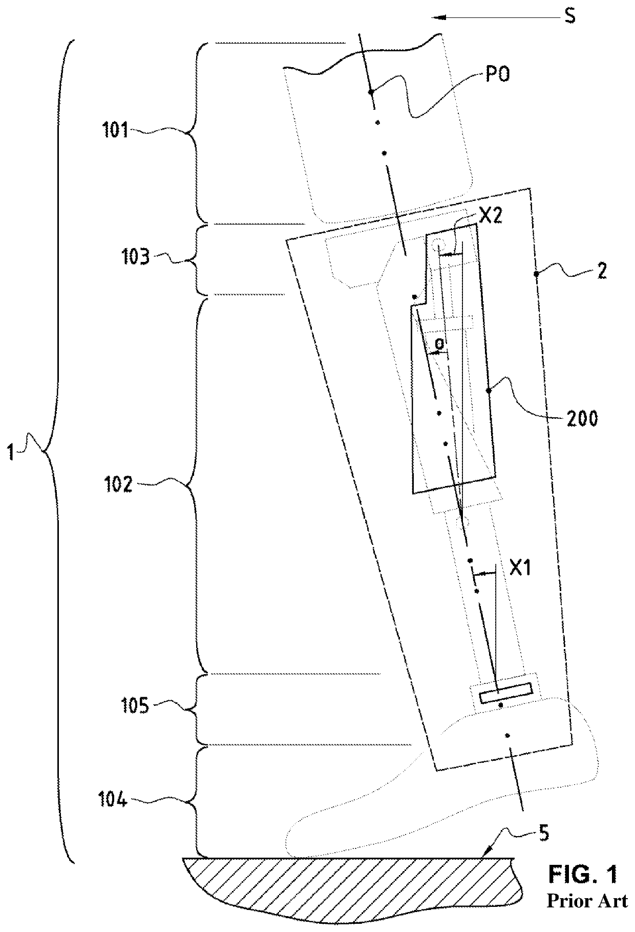
[0024]FIG. 1 is a profile view of a swing and stance type prosthesis which will be referred to from now on simply as an “SNS” prosthesis.

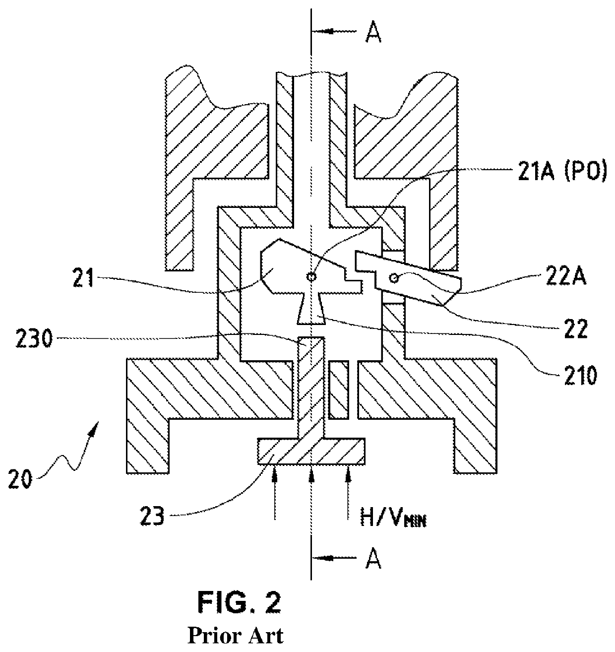
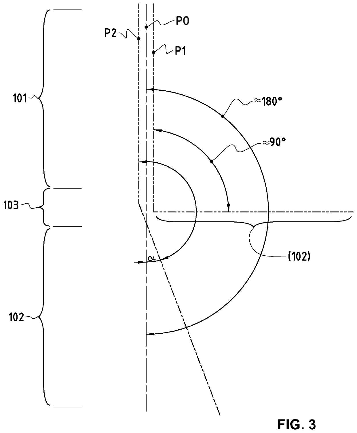
[0025]The prosthesis 1 conventionally comprises a femoral part 101, ending the thigh, and intended to be adjusted on the stump of the amputee, as well as a tibial part 102 replacing the amputee's leg, and a foot part 104 replacing the amputee's foot, with a view to ensure taking support on a support surface 5, typically the ground or floor. So as to ensure an articulated connection between the femoral part 101 and the tibial part 102 of the prosthesis, the intermediate knee part 103 which connects them comprises a hinged connecting device 2 simulating this articulation by providing a degree of freedom in limited rotation between a first position P0 of hyperextension, in which the femoral part 101 and the tibial part 102 extend substantially in the prolongation one from the other, and a second position P1 of maximal flexion, illustrated further on i...


PUM


Abstract

A hinged connecting device comprising a damping mechanism intended to counter a predetermined resistance at least during bending of the prosthesis (1), by replacing the muscle groups usually used for this purpose. The damping mechanism (200) is capable of being switched between a first operating mode (M1), selected by default, in which the value of the resistance corresponds to a first maximum value (Vmax), and a second operating mode (M2), that can be actuated only in a hyperextension position (P0) of the prosthesis (1), in which the resistance value corresponds to a second minimum value (Vmin); and the hinged connecting device (2) moreover comprises a fully mechanical locking system (3), arranged in order to allow the second operating mode (M2) to be activated only when the inclination of the tibial part (102) exceeds a first predetermined oriented angle (X1) relative to the vertical.

Description

TECHNICAL FIELD OF THE INVENTION[0001]This invention relates to the field of knee prostheses for a femoral amputee, and more specifically to fully mechanical knee prostheses, that is to say devoid of any sensor or electronic control system.STATE OF THE ART[0002]In order to make it possible to simulate at best the articulation of a healthy knee, recent developments have sought to provide prostheses with sophisticated integrated electronic systems to determine and control the flexion of the tibial part with respect to the femoral part, based on position and acceleration data obtained from various sensors. One drawback of this type of solution is that it requires especially efficient processors to process the sensor data and implement relatively complex algorithms designed to ensure the stability of the wearer, all the while reproducing the most natural possible movement of the leg. Firstly, this type of solution turns out to be particularly cumbersome to systematically ensure a suffic...

Claims


Application Information

Patent Timeline
Patent Type & Authority Patents(United States)
IPC IPC(8): A61F2/64A61F2/74A61F2/68A61F2/50A61F2/60A61F2/66A61F2/76
CPCA61F2/64A61F2/68A61F2/74A61F2002/5006A61F2002/5018A61F2002/5021A61F2002/5038A61F2002/607A61F2002/608A61F2002/6614A61F2002/6836A61F2002/6854A61F2002/7625A61F2002/5033A61F2002/5036A61F2/748
Inventor STEINER, JEAN-LOUISSCHNEIDER, CLÉMENT
Owner S & S SARL
Learn More