
Combined circular groove for butterfly valve seat of molecular sieve

A butterfly valve seat and combination ring technology, applied in the direction of lift valve, valve device, engine components, etc., can solve the problems of easy leakage, high processing cost, short life, etc., to ensure two-way sealing, improve performance level, and prolong service life Effect

Active Publication Date: 2010-11-17
NEWTORK FLOW CONTROL CO LTD
View PDF8 Cites 1 Cited by
  • Summary
  • Abstract
  • Description
  • Claims
  • Application Information

AI Technical Summary

Problems solved by technology

Due to processing errors and structural reasons, ordinary soft-sealed butterfly valves have a short service life and are prone to leakage, which cannot meet the needs of working conditions.
[0003] Butterfly valves are divided into neutral butterfly valves, single eccentric butterfly valves, double eccentric butterfly valves, and triple eccentric butterfly valves according to their structure. Among them, the triple eccentric butterfly valve has the best performance, but cannot achieve bidirectional sealing. Therefore, the traditional solution is to use double eccentric butterfly valves to reduce The wear of the valve plate and the valve seat improves the mutual sealing performance; however, the valve seat of the traditional butterfly valve is made of polytetrafluoroethylene material, the structure of the valve seat is complex, and it is difficult to process and shape. The material is greatly affected by temperature and humidity, and the forming accuracy of the valve seat The requirements are relatively high, even if the error is large in different weathers in the same area, not only the processing cost is high, but the most important thing is that the universal type and batch production of the valve seat are limited
At the same time, if the "piston ring benefit" of the valve seat is realized and the performance of the valve is improved, the structure is more complicated, the manufacturing cost is high, and the performance is not stable

Method used


Image

  • Combined circular groove for butterfly valve seat of molecular sieve
  • Combined circular groove for butterfly valve seat of molecular sieve
  • Combined circular groove for butterfly valve seat of molecular sieve

Examples


Embodiment Construction

[0020] The present invention will be further described below in conjunction with the accompanying drawings.

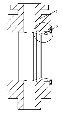
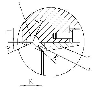
[0021] Such as figure 1 and figure 2 As shown, the present invention provides a combined ring groove for the valve seat of a molecular sieve butterfly valve. The combined ring groove has three sections of circular arc surfaces with equal radii, two of which are on the valve body 1, and one section is on the pressure ring 2. The two arc surfaces on the valve body 1 are connected by two arc surfaces with a radius R and a center distance H concave inward. One side of the valve body 1 is screwed to the pressure ring 2, and the root of the pressure ring 2 is provided with a The concave arc surface 21 forms a combined ring groove 3 with the arc surface on the valve body 1 . The radius of the arc surface 21 at the root of the pressure ring 2 is R, and the center of the arc surface 21 coincides with the center of the arc surface of the inner section of the valve body 1 .

...


PUM


Abstract

The invention discloses a combined circular groove for a butterfly valve seat of a molecular sieve. The butterfly valve seat is a fluororubber O-shaped ring valve seat made from an abrasion-proof material; a sunken circular groove is reserved on the inner surface of a circular passageway of the valve seat; the O-shaped ring valve seat is arranged in the circular groove; the arched surface of the circular groove consists of two arcs, wherein the radius of each arc is R and a space between the centers of circles of the arcs is H; the valve seat on one side of the circular groove is screwed with a pressure ring; the root part of the pressure ring is provided with the sunken arched surface; and the arched surface and the circular groove form the combined circular groove. The combined circular groove is a special product applied to the strict working conditions of the cutting-off and control of air in an air separation system, changes the structural form of the conventional butterfly valve seat, realizes the 'piston ring effect', prolongs the service life of a valve, ensures two-way sealing and improves the performance level of the valve, along with simple structure, low cost and easy machining.

Description

technical field [0001] The invention relates to a combined ring groove for installing a valve seat, in particular to a combined ring groove suitable for the valve seat of a molecular sieve butterfly valve in an air separation device. Background technique [0002] The cut-off valve designed for the control of air in the air separation system is a special product used in severe working conditions. Air containing water vapor, carbon dioxide, hydrocarbons and other tiny solid particles must be removed before the air can be cooled and separated. The effective way to remove it is to use molecular sieve adsorption. Generally, two adsorption dryers are used in parallel, one works, and the other can be regenerated at the same time. Frequent alternate work and regeneration are used to ensure continuous operation of the equipment. Therefore, butterfly valves are required not only to have a long life, but also to achieve bidirectional sealing. Ordinary soft-sealed butterfly valves ...

Claims


Application Information

Patent Timeline
Patent Type & Authority Applications(China)
IPC IPC(8): F16K1/42F16K1/22
Inventor 卓育成卓团结郭风忠卓集中
Owner NEWTORK FLOW CONTROL CO LTD
Learn More