


Quick Research
Generate reliable direction feasibility study reports for your R&D in just a few steps.

Technical Q&A
Discover and master advanced knowledge NOW. Basics, ideas, possibilities, all at once.

Find Solutions
As an expert in R&D theories, this can generate solutions to your technical problems instantly.

Evaluate Feasibility
Analyze your overall solution with one click, know your potential R&D risks in advance.

Monitor Landscape
Get weekly tech updates, stay abreast of the latest tech innovations and key insights.
Shield device for annular permanent magnet
A technology of shielding device and permanent magnet, which is applied in the direction of synchronous machine parts, etc., can solve the problems of non-existence, imperfect overall structure, and inability to realize shielding, and achieve the effects of reducing magnetic energy loss, uniform force, and increasing output power
- Summary
- Abstract
- Description
- Claims
- Application Information
AI Technical Summary
Problems solved by technology
Method used
Image

Examples
Embodiment 1
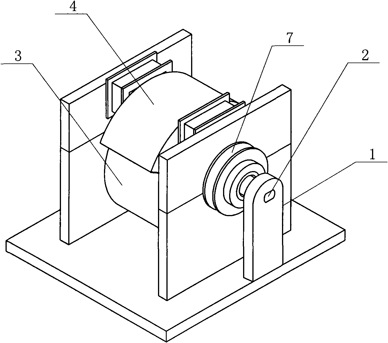
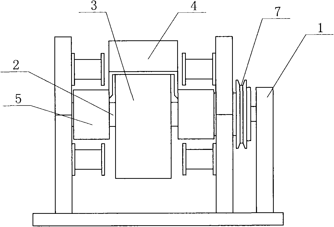
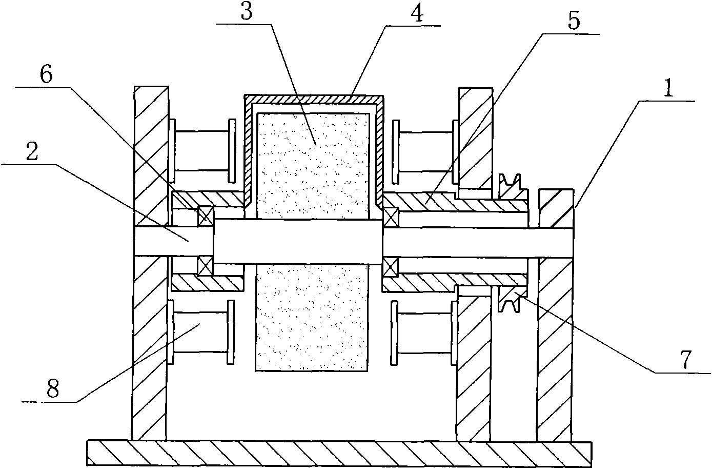
[0030] see Figure 1 to Figure 3 As shown, the annular permanent magnet shielding device of the present embodiment has a frame 1, a central axis 2 is fixed on the frame, an annular permanent magnet 3 is installed on the central axis, and the annular permanent magnet and the central axis form Interference installation, a rotating shield body 4 is arranged outside the annular permanent magnet; Shape), the rotating shield body is installed on the central axis through the rotating connector 5, this embodiment is provided with two rotating connectors, respectively arranged on both sides of the rotating shielding body, the rotating connecting member and the two sides of the rotating shielding body The wall is fixedly connected, and a bearing 6 is respectively provided in the two rotating connectors; thereby realizing the rotating connection between the rotating shield and the central shaft; a power input wheel 7 is installed with the rotating connector; described in this embodiment ...
Embodiment 2
[0038] This embodiment is a technical solution improved on the basis of the first embodiment, and the same parts as the first embodiment will not be described in detail. see Figure 5 , Figure 6As shown, a magnetically conductive sleeve 9 is set outside the central shaft, and the magnetically conductive sleeve is installed between the central shaft and the annular permanent magnet, and the two ends of the magnetically conductive sleeve slide with the rotating shield The two ends of the magnetic conductive sleeve are provided with contact surfaces 10 corresponding to the rotating shield. This embodiment adopts such a design, which can make the magnetic conducting sleeve and the rotating shield form a magnetic conducting circuit; when the rotating shield shields a part of the magnetic field of the annular permanent magnet, the magnetic field lines 13 of the N pole of this part of the magnetic field cannot penetrate Correspondingly, the left side wall of the rotating shield ha...
Embodiment 3
[0040] This embodiment is a technical solution improved on the basis of the second embodiment, and the same parts as the second embodiment will not be described in detail. see Figure 7 , Figure 8 As shown, a helical excitation coil 11 is sheathed outside the magnetic conduction sleeve, and the excitation coil is installed between the magnetic conduction sleeve and the annular permanent magnet, and passes through the positioning collars 12 installed on both sides of the excitation coil. fixed. During the regenerating process, the power generation coil will generate an attractive force on the rotating shielding body, hindering the rotation of the shielding body; therefore, an electric current can be input on the exciting coil to make the exciting coil generate a magnetic pole in the same direction as the annular permanent magnet. Under the action of current, the magnetic field lines 14 introduced into the rotating shielding body are instantly saturated and penetrate the rota...
PUM
 Abstract
Description
Claims
Application Information
 - R&D Engineer
- R&D Manager
- IP Professional
- Industry Leading Data Capabilities
- Powerful AI technology
- Patent DNA Extraction
Browse by: Latest US Patents, China's latest patents, Technical Efficacy Thesaurus, Application Domain, Technology Topic, Popular Technical Reports.
© 2024 PatSnap. All rights reserved.Legal|Privacy policy|Modern Slavery Act Transparency Statement|Sitemap|About US| Contact US: help@patsnap.com