
Liquid crystal point reversing drive circuit

A drive circuit and dot inversion technology, which is applied to instruments, static indicators, etc., can solve the problems of high energy consumption and large volume, and achieve the effects of reducing energy consumption, reducing volume, and reducing energy consumption and volume

Inactive Publication Date: 2010-11-03
SITRONIX TECH CORP
View PDF40 Cites 7 Cited by
  • Summary
  • Abstract
  • Description
  • Claims
  • Application Information

AI Technical Summary

Problems solved by technology

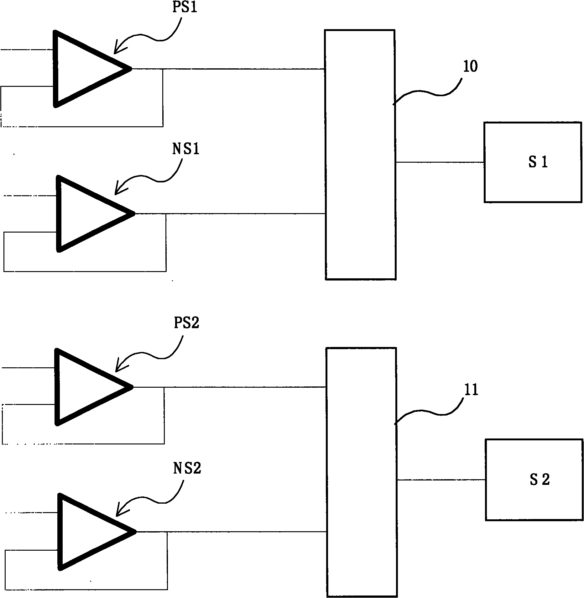
In fact, the first high-voltage selection circuit 10' and the second high-voltage selection circuit 11' are composed of high-voltage process components, so they have the disadvantages of large volume and high energy consumption

Method used


Image

  • Liquid crystal point reversing drive circuit
  • Liquid crystal point reversing drive circuit
  • Liquid crystal point reversing drive circuit

Examples


Embodiment Construction

[0034] The present invention will be further described below in conjunction with drawings and embodiments.

[0035] The liquid crystal point inversion drive circuit of the flat panel display in ideal embodiment of the present invention can be applied to the signal drive system of various liquid crystal displays (Liquid Crystal Display, LCD), but is not used for limiting the liquid crystal point inversion drive circuit in the present invention application range.

[0036] Figure 5 It is a schematic block diagram of the first embodiment of the liquid crystal point inversion driving circuit of the present invention. As shown in the figure, the liquid crystal point inversion driving circuit in the first embodiment of the present invention includes a positive signal source 20, a negative signal source 21, a first selection unit 30, a second selection unit 31, a first signal source S1 and a second signal Source S2.

[0037] like Figure 5 As shown, the positive signal source 20 ...


PUM


Abstract

The invention provides a liquid crystal point reversing drive circuit, comprising a positive signal source, a negative signal source, a first selection unit and a second selection unit, wherein, the positive signal source provides a first positive signal and a second positive signal; the negative signal source provides a first negative signal source and a second negative signal source; the first selection unit is connected with the positive signal source and the negative signal source and used for receiving the first positive signal of the positive signal source and the first negative signal of the negative signal source, and the unit is composed of low-voltage elements; the second selection unit is connected with the positive signal source and the negative signal source and used for receiving the second positive signal of the positive signal source and the second negative signal of the negative signal source, and the unit is composed of low-voltage elements; the first signal source is connected with the first selection unit to alternately output a first positive voltage and a first negative voltage; and the second signal source is connected with the second selection unit to alternately output a second positive voltage and a second negative voltage. The drive circuit forms output of the positive voltage and the negative voltage of two source electrodes by single positive signal source and single negative signal source, thus reducing the usage quantity of a computing amplifier.

Description

technical field [0001] The invention relates to a liquid crystal dot inversion driving circuit, in particular to a simplified liquid crystal dot inversion driving circuit. Background technique [0002] Generally speaking, multiple pixels of an existing flat panel display are controlled by corresponding multiple thin film transistors (TFTs) (not shown), so as to control a liquid crystal display (LCD display) to display desired images. Several gate driving lines of the flat panel display are connected to gates of corresponding thin film transistors to control switching operations of these thin film transistors. [0003] like figure 1 As shown, the two frames in the figure represent the polarity of the liquid crystal capacitor gate (gate) and signal source (source) when the liquid crystal capacitor is charged at the voltage polarity change point reversed. The two frames are respectively the first frame N and the second frame N+1. For example, the first frame N and the second...

Claims


Application Information

Patent Timeline
IPC IPC(8): G09G3/36
Inventor 洪德儒林春生叶政忠
Owner SITRONIX TECH CORP
Learn More