
Automatic lifting system

A technology of automatic lifting and lifting device, applied in the direction of lifting frame, lifting device, etc., can solve problems such as increased maintenance cost, complex structure, and device quality problems

Inactive Publication Date: 2010-11-03
DONGGUAN ANWELL DIGITAL MASCH CO LTD
View PDF5 Cites 23 Cited by
  • Summary
  • Abstract
  • Description
  • Claims
  • Application Information

AI Technical Summary

Problems solved by technology

Its bearing capacity is strong, but most of them have complicated structures, and they are very noisy during the working process, and the movement accuracy is not high.
Usually, this kind of lifting device is generally placed inside a cavity, and the particles and dust caused by the friction of the parts during the lifting movement stay in the cavity, which is very easy to pollute the production process environment in the cavity. At the same time, it is easy to Cause gas and products in the process to react with the device, resulting in problems with the quality of the device, resulting in increased maintenance costs
Therefore, the traditional lifting device cannot well adapt to the needs of the production line in the vacuum environment industry

Method used


Image

  • Automatic lifting system
  • Automatic lifting system
  • Automatic lifting system

Examples


Embodiment Construction

[0017] The present invention will be further described below in conjunction with preferred embodiments and accompanying drawings, but the embodiments of the present invention are not limited thereto.

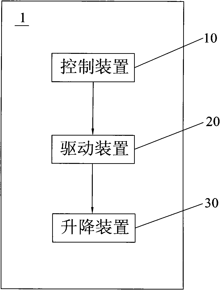
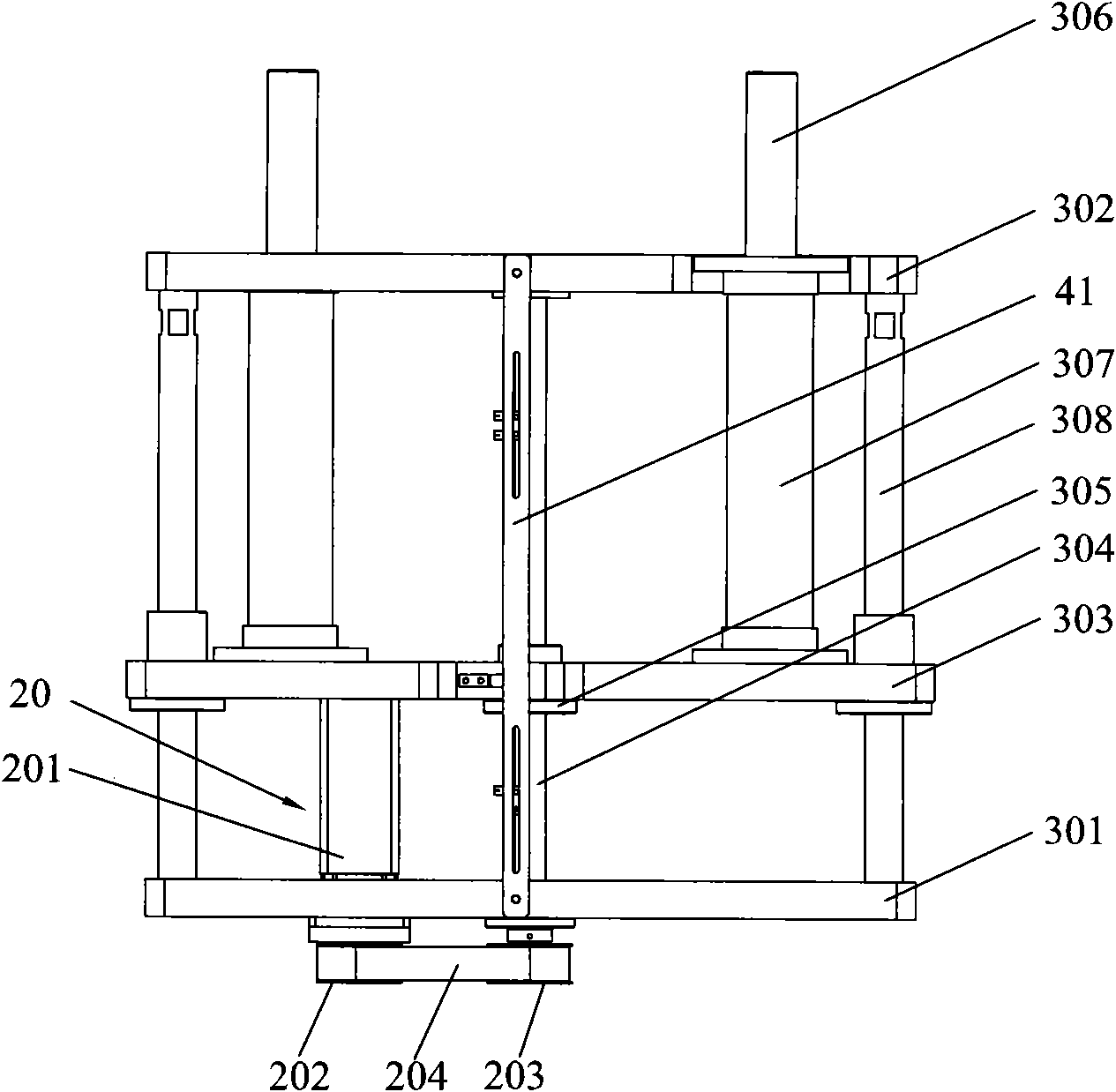
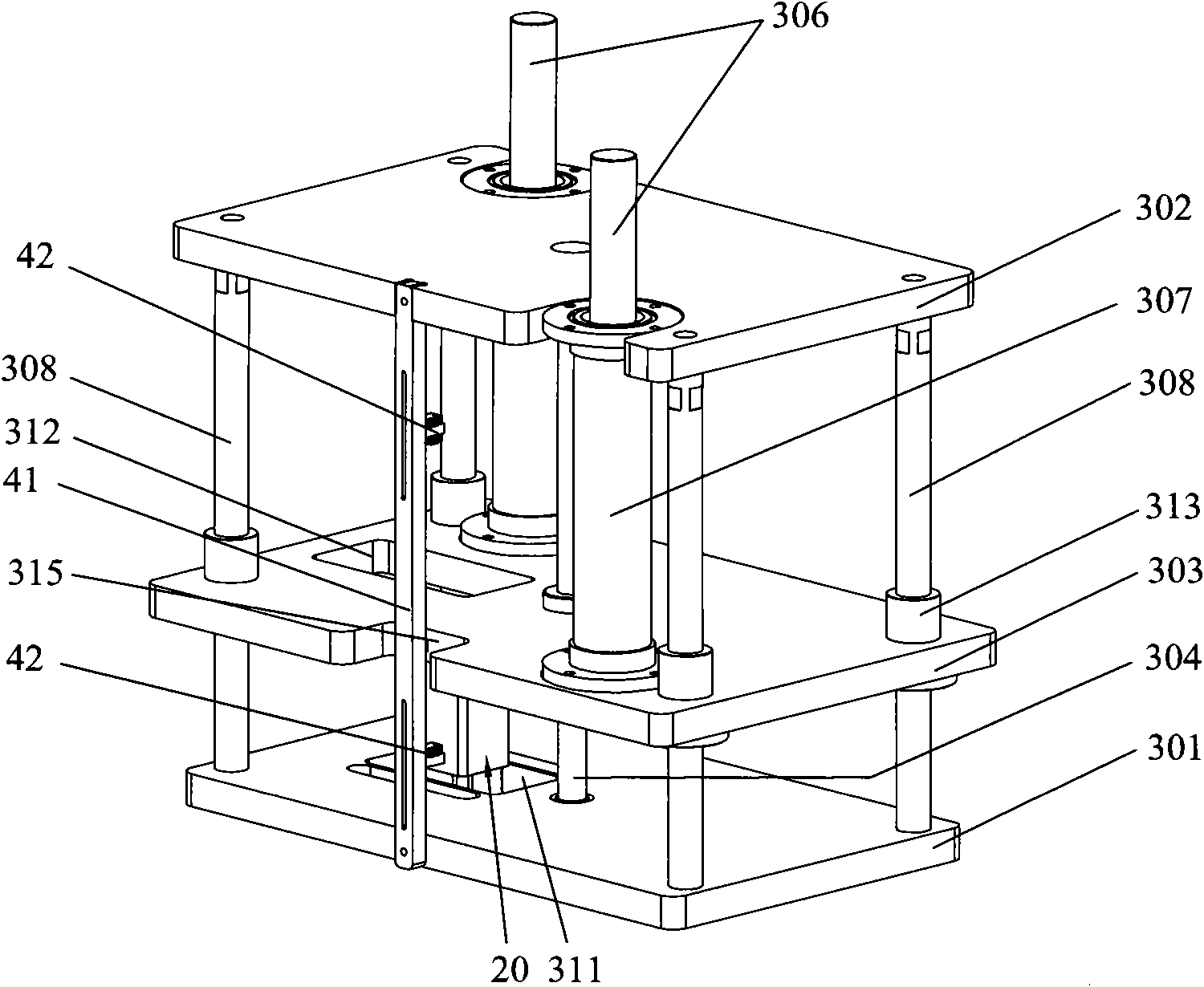
[0018] Please refer to figure 1 and figure 2 , The automatic lifting system 1 of the present invention includes a control device 10 , a driving device 20 and a lifting device 30 . The lifting device 30 is connected to an external workbench (not shown), the control device 10 is electrically connected to the driving device 20, and the control device 10 drives the driving device 20 so that the lifting device 30 drives the external workbench to perform linear reciprocating motion. The components and control methods of the automatic lifting system 1 of the present invention will be described in detail below.

[0019] Such as Figure 2-4 As shown, the lifting device 30 includes a first fixed plate 301 , a second fixed plate 302 , a movable plate 303 , a lead screw 304 , a lead scr...


PUM


Abstract

The invention discloses an automatic lifting system. The automatic lifting system comprises a control device, a driving device and a lifting device which are electrically connected together, wherein the driving device and the lifting device are controlled by the control device; the lifting device is connected with an external work table; the control device drives the driving device, so that the lifting device drives the external work table to make straight reciprocating motion; the lifting device comprises a first retaining plate, a second retaining plate, a movable plate, a lead screw, a lead screw nut and a supporting column; the movable plate is arranged between the first retaining plate and the second retaining plate; the driving device is fixed to the first retaining plate; the lead screw nut is inserted into and fixed on the movable plate; one end of the lead screw passes through the first retaining plate and is connected with the driving device, while the other end passes through the lead screw nut and then is connected with the second retaining plate; and one end of each supporting column is fixed to the movable plate, while the other end passes through the second retaining plate and protrudes on the second retaining plate to be connected with the external work table. The system has the advantages of high movement accuracy, high reliability, low noise, low pollution and simple structure.

Description

technical field [0001] The invention relates to an automatic lifting system, more particularly to an automatic lifting system for lifting finished or semi-finished products on a production line in a vacuum environment industry. Background technique [0002] Lifting devices are widely used in industrial equipment. For example, in the vacuum field, semiconductor transmission, photolithography and other processes require lifting devices to realize the lifting movement of finished or semi-finished products. The motion accuracy and reliability of the lifting device often become the key to the operation of the equipment. [0003] Traditional lifting methods include hydraulic method, pneumatic method, mechanical screw method and so on. The hydraulic method has relatively large jacking force and good self-locking performance, but the technical requirements for implementing this method are relatively high. If a hydraulic lifting device is used, its structure is complex, its machini...

Claims


Application Information

Patent Timeline
Patent Type & Authority Applications(China)
IPC IPC(8): B66F7/06B66F7/28
Inventor 杨明生郭业祥刘惠森范继良王曼媛王勇张华
Owner DONGGUAN ANWELL DIGITAL MASCH CO LTD
Learn More