Reduction gear and control method thereof

A technology of deceleration device and deceleration mechanism, which is applied in the direction of control system, single motor speed/torque control, computer control, etc. It can solve the problems of high price of photoelectric encoder, great influence of vibration and dust, and low accuracy of potentiometer detection angle, etc. question

Inactive Publication Date: 2013-03-06
杭州中科赛思伺服电机有限公司
View PDF1 Cites 0 Cited by
  • Summary
  • Abstract
  • Description
  • Claims
  • Application Information

AI Technical Summary

Problems solved by technology

Photoelectric encoders are expensive and have high requirements for the use environment, and vibration and dust have a great impact on them
Potentiometer detection angle accuracy is very low, as a contact sensor, low reliability, and inconvenient to use
The document whose application number is 200620013049 discloses a full-closed-loop servo rotary table, an encoder is installed on the working shaft, and the cost is high

Method used


Image

  • Reduction gear and control method thereof
  • Reduction gear and control method thereof
  • Reduction gear and control method thereof

Examples


Embodiment 1

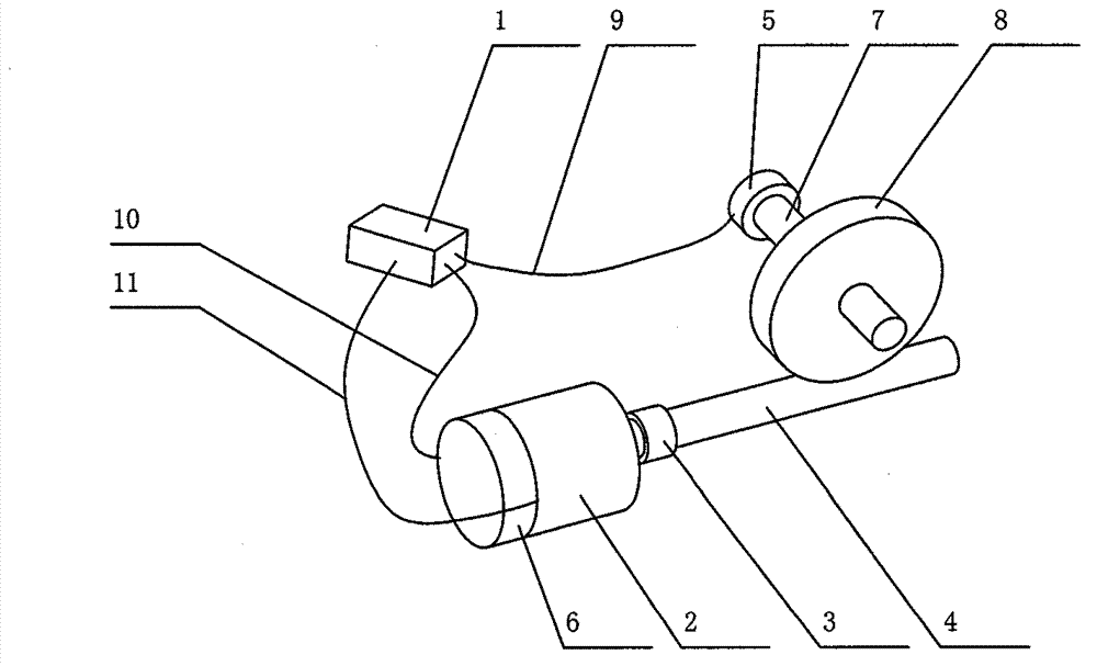
[0106] figure 1 It is a structural schematic diagram of the reduction gear transmission according to Embodiment 1 of the present invention. Such as figure 1 As shown, the deceleration device includes a servo controller 1, a servo motor 2 and a deceleration mechanism connected thereto. The deceleration mechanism is composed of a driving part and a driven part that cooperate with each other. In this embodiment, the driving part refers to the worm 4, and the driven part is The worm gear 8, the servo motor is connected with the worm 4 through the coupling 3, and the worm 4 cooperates with the worm gear 8 to input the power of the servo motor 2 and output it after deceleration. The input shaft of the servo motor 2 and the output shaft of the reduction mechanism are the worm shaft 7 A first position detection device 5 and a second position detection device 6 are respectively provided, and the first position detection device 5 and the second position detection device 6 input signals...


PUM


Abstract

A speed reduction device and its control method are provided. The speed reduction device includes a servo motor and a speed reducing mechanism connected with the servo motor. The speed reducing mechanism consists of a driving part and a driven part matched with each other. The servo motor is connected to the driving part by a coupling. The driving part matches with the driven part, and introduces the power from the servo motor and outputs it after speed reducing. The input shaft of said servo motor and the output shaft of the speed reducing mechanism are respectively equipped with a first and a second position detecting device. Said position detecting devices input signals to a servo controller by signal line, and the servo controller outputs a voltage to the servo motor. The servo motor drives the speed reducing mechanism to run, which outputs the power input of the servo motor after speed reducing. Said speed reduction device has low cost, high control accuracy, fast response, controllable torque and controllable rotational speed. Said speed reduction device facilitates the networking and integration of control, and can receive commands from a general controller to control the operation of manipulator with full closed loop control.

Description

technical field [0001] The invention relates to a deceleration device and a control method of the deceleration device. Background technique [0002] The reducer is a power transmission mechanism that uses the speed converter of the gear to reduce the number of revolutions of the motor to the desired number of revolutions and obtain a larger torque mechanism. Reduce the speed and increase the output torque at the same time. The torque output ratio is the motor output multiplied by the reduction ratio, but attention should be paid not to exceed the rated torque of the reducer. The speed reduces the inertia of the load at the same time, and the reduction of the inertia is the square of the reduction ratio. You can look at the general motor has an inertia value. General reducers include helical gear reducers, including parallel shaft helical gear reducers, worm gear reducers, bevel gear reducers, planetary gear reducers, cycloidal pin wheel reducers, worm gear reducers, planet...

Claims


Application Information

Patent Timeline
Patent Type & Authority Patents(China)
IPC IPC(8): B25J13/00G05B19/04H02P6/08
CPCG05B15/02H02P17/00
Inventor 郝双晖郝明晖
Owner 杭州中科赛思伺服电机有限公司
Why Eureka
Try Eureka