


Quick Research
Generate reliable direction feasibility study reports for your R&D in just a few steps.

Technical Q&A
Discover and master advanced knowledge NOW. Basics, ideas, possibilities, all at once.

Find Solutions
As an expert in R&D theories, this can generate solutions to your technical problems instantly.

Evaluate Feasibility
Analyze your overall solution with one click, know your potential R&D risks in advance.

Monitor Landscape
Get weekly tech updates, stay abreast of the latest tech innovations and key insights.
Hydraulic liner releaser and release method for oil and gas wells
A technology for oil and gas wells and releasers, which is applied in earthwork drilling, wellbore/well components, sealing/isolation, etc. It can solve the difficulties of liner release and identification, failure to disengage liner with carrying liner, difficulty in guaranteeing construction quality, etc. problems, to achieve easy expansion locking and contraction reset, avoid sticking straps and buckling difficulties, and achieve reliable locking effects
- Summary
- Abstract
- Description
- Claims
- Application Information
AI Technical Summary
Problems solved by technology
Method used
Image

Examples
Embodiment 1
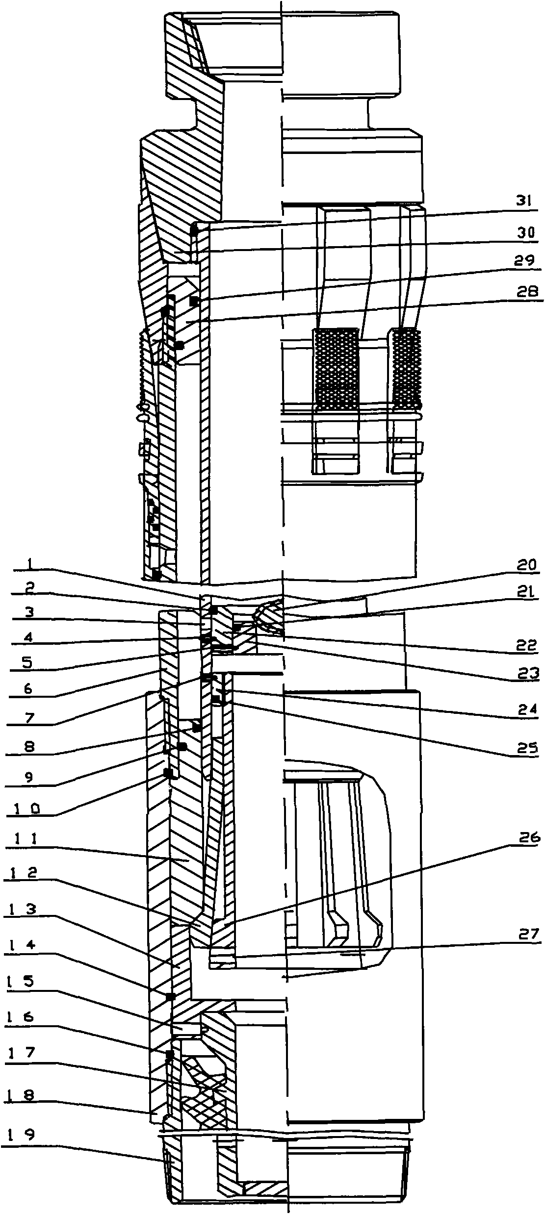
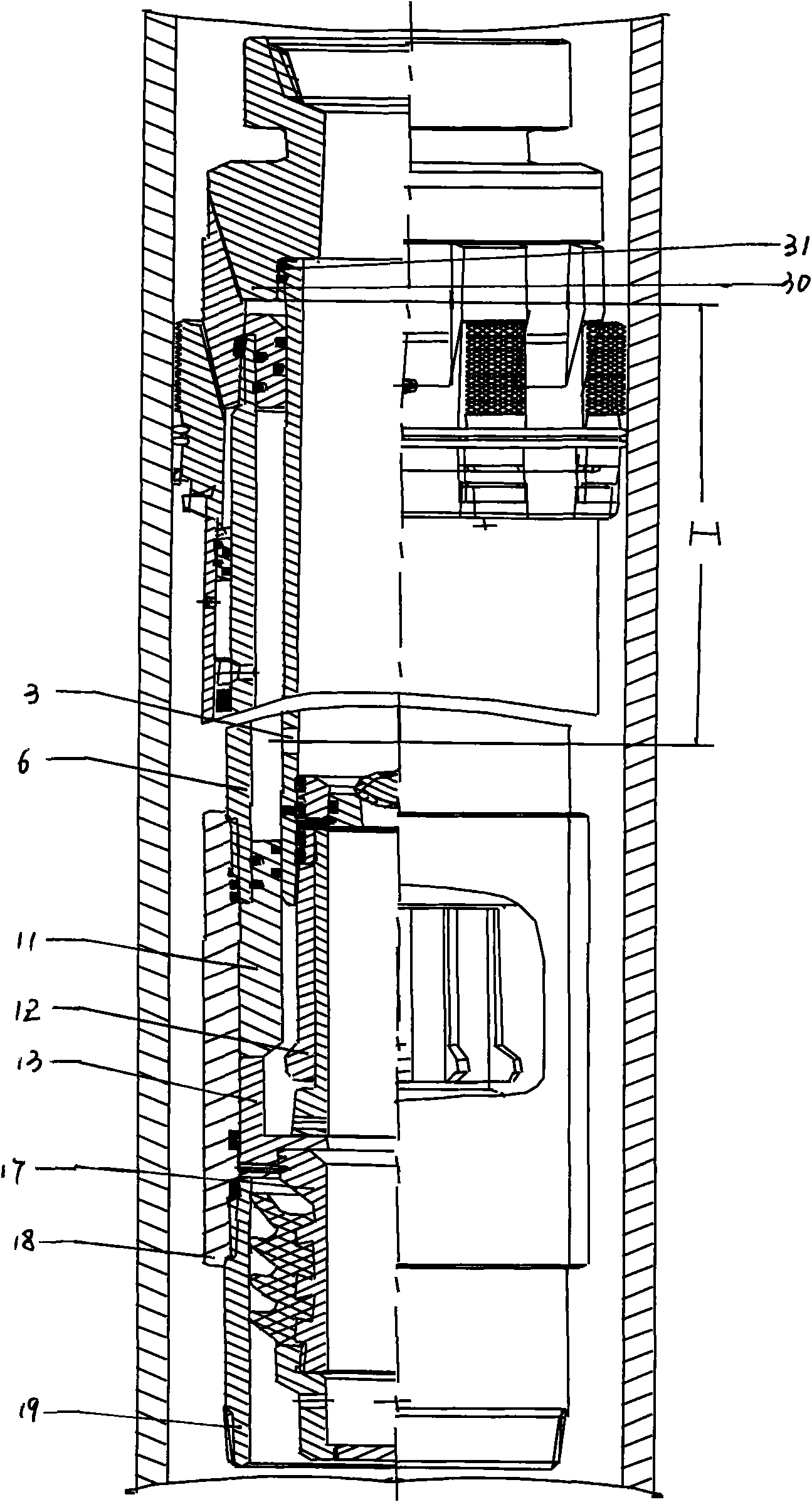
[0040] A hydraulic tailpipe releaser for oil and gas wells, including a housing 18, an insertion pipe 1, a locking mechanism and an unlocking mechanism. One end of the housing 18 is sealed and connected to the hanger double male short-connect 6, and the other end is sealed with the tail pipe short-connect 19. connection; one end of the insertion pipe 1 is sealed and connected with the drill pipe short 30, and the other end is connected with the locking mechanism arranged in the housing 18, and the insertion pipe 1 is provided with a pressure transmission hole 3 leading to the hydraulic cylinder; The lock mechanism includes a lock sleeve 11, a reset lock lock 12, a support seat 13, a lock cap 24 and a lock cylinder 26. One end of the lock sleeve 11 is sealed between the insertion tube 1 and the hanger double male short-circuit 6, and the other end is located at the support base. 13, the upper end of the reset lock hanger 12 is connected with the insertion tube 1 and the lower en...
Embodiment 2
[0052] The invention includes a shell, an insertion tube, a locking mechanism and an unlocking mechanism. The upper end of the housing 18 is threaded to the lower end of the double male short connector 6 of the hanger, the lower end of the housing 18 is connected to the tailpipe short connector 19 by threads, and the insertion pipe 1 is connected by a locking mechanism in the housing 18. The insertion pipe 1 is threadedly connected to the lower end of the drill pipe short connection 30, the insertion pipe 1 is inserted into the hanger, and its upper part forms a sealing structure with the hanger sealing sleeve 28, and the lower part of the insertion pipe 1 is provided with a pressure transmission hole leading to the hanger hydraulic cylinder 3 and link to each other with unlocking mechanism and locking mechanism.
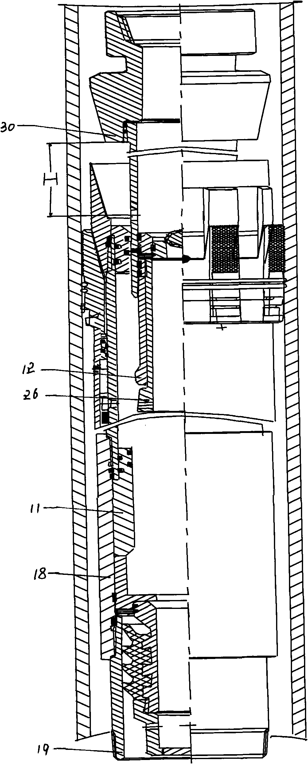
[0053] The locking mechanism is composed of a lock sleeve 11, a reset lock lock 12, a support seat 13, a lock cap 24, and a lock cylinder 26. The lower end is loca...
Embodiment 3
[0061] In the release method of the present invention, controlling the hydraulic pressure includes controlling the hydraulic pressure inside the liner drill string, inside the drill pipe short and inside and outside the insertion pipe, and lifting the drill string includes lifting the drill string on the wellhead to leave the wellhead rotary table surface. Measuring the lifting degree includes measuring the height of the lifting drill string from the wellhead turntable surface, so that the pressure transmission hole at the lower part of the insertion pipe moves up with the drill string to the seal sleeve of the hanger, so as to achieve the communication and discharge of the inside and outside of the drill string. When it is lifted to a certain height, it can be judged whether the insertion tube is disconnected from the tail pipe connection, that is, whether the tail pipe release is successful or not, by observing the change of the pressure gauge.
[0062] During implementation,...
PUM
 Abstract
Description
Claims
Application Information
 - R&D Engineer
- R&D Manager
- IP Professional
- Industry Leading Data Capabilities
- Powerful AI technology
- Patent DNA Extraction
Browse by: Latest US Patents, China's latest patents, Technical Efficacy Thesaurus, Application Domain, Technology Topic, Popular Technical Reports.
© 2024 PatSnap. All rights reserved.Legal|Privacy policy|Modern Slavery Act Transparency Statement|Sitemap|About US| Contact US: help@patsnap.com