
Rolling type centrifugal casting machine

A centrifugal casting machine and supporting roller technology, applied in the field of centrifugal casting equipment, can solve the problems of inconvenient installation and operation, restricted casting length, time-consuming installation, etc., and achieve the effect of simple structure and low production cost.

Inactive Publication Date: 2010-10-27
武胜县锦雄机械有限责任公司
View PDF4 Cites 5 Cited by
  • Summary
  • Abstract
  • Description
  • Claims
  • Application Information

AI Technical Summary

Problems solved by technology

[0002] See Figure 4 As shown, the existing centrifugal casting machine is usually a horizontal cantilever centrifugal casting machine. This kind of centrifugal casting machine has a complex structure, especially one end of the casting mold 11 is connected to the shaft end of the main shaft 12 to form a cantilever state. The rotation of the main shaft drives the rotation of the casting mold. The molten metal injected into the mold is cast into shape under the action of centrifugal force
This cantilever centrifuge has a cantilever shape because the casting mold is installed on the main shaft. In order to avoid the rotation and swing of the suspended end of the casting mold when it rotates with the main shaft, which will affect the molding of the casting, the axial length of the casting mold is relatively short, generally not exceeding 400mm. It is used to install the connecting end part, and the axial length of the cast casting is shorter, so that the length of the cast casting is restricted
Moreover, the casting mold needs to be fixedly connected with the main shaft in the circumferential direction. In order to avoid the rotation and swing of the main shaft shaft end, the bearing seat at the end connecting the main shaft and the casting mold will be as close as possible to the shaft end, and the journal sleeve at the connecting end of the casting mold and the main shaft will be shortened as much as possible. This results in a narrow space between the casting mold and the main shaft, which makes the installation operation when the casting mold and the main shaft are fixedly connected in the circumferential direction very inconvenient and time-consuming to install.

Method used


Image

  • Rolling type centrifugal casting machine
  • Rolling type centrifugal casting machine
  • Rolling type centrifugal casting machine

Examples


Embodiment Construction

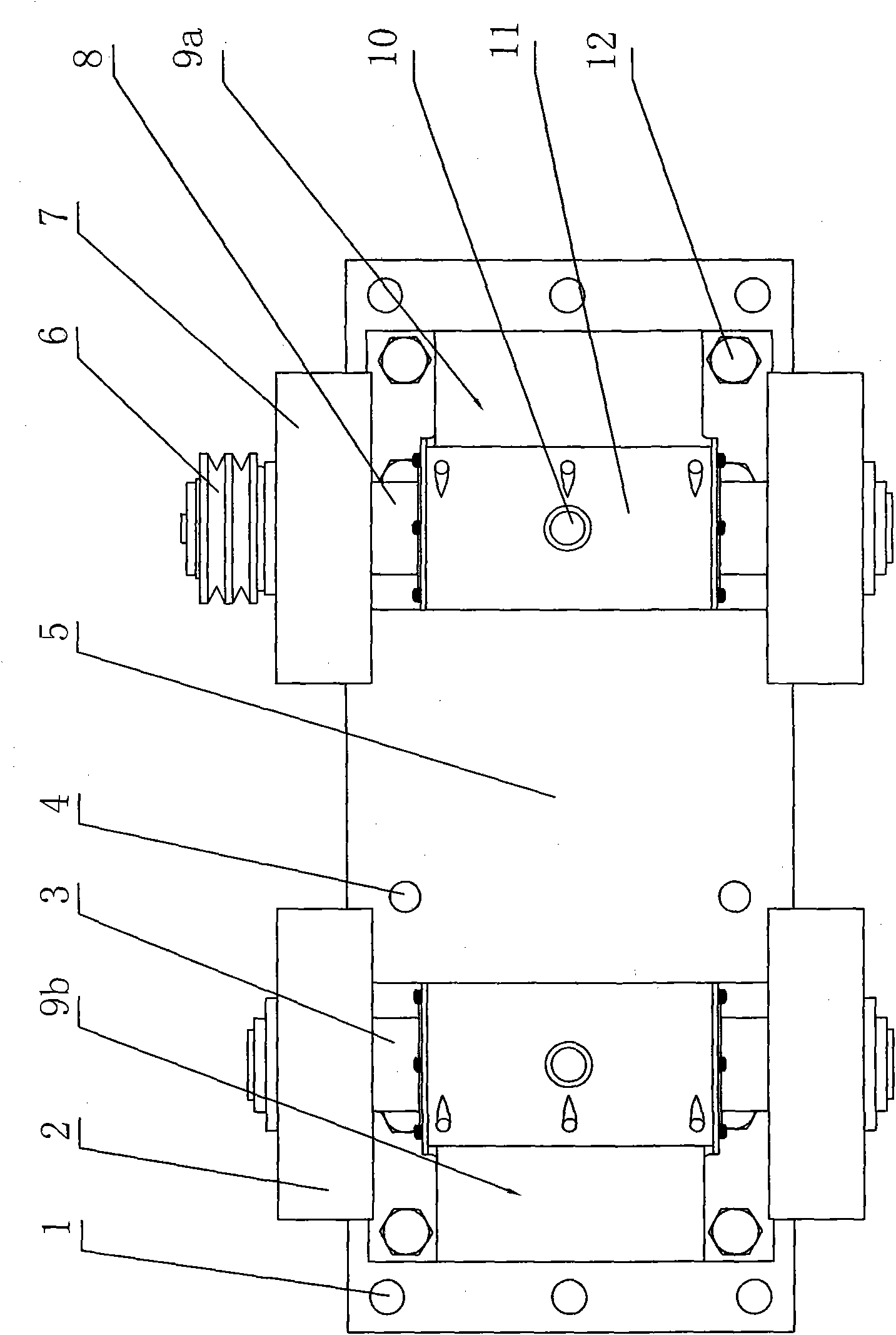
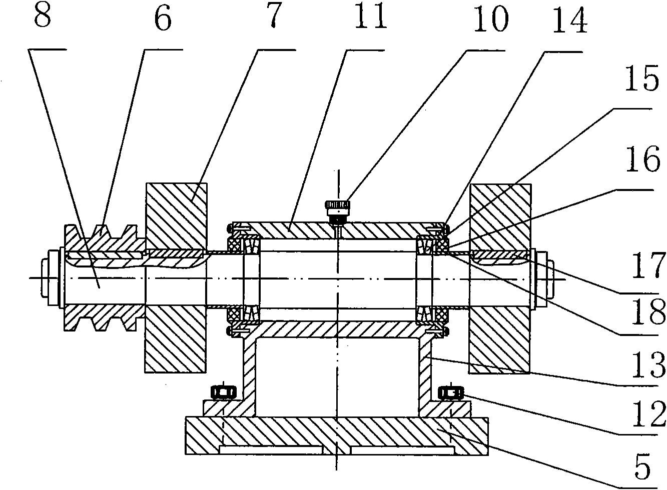
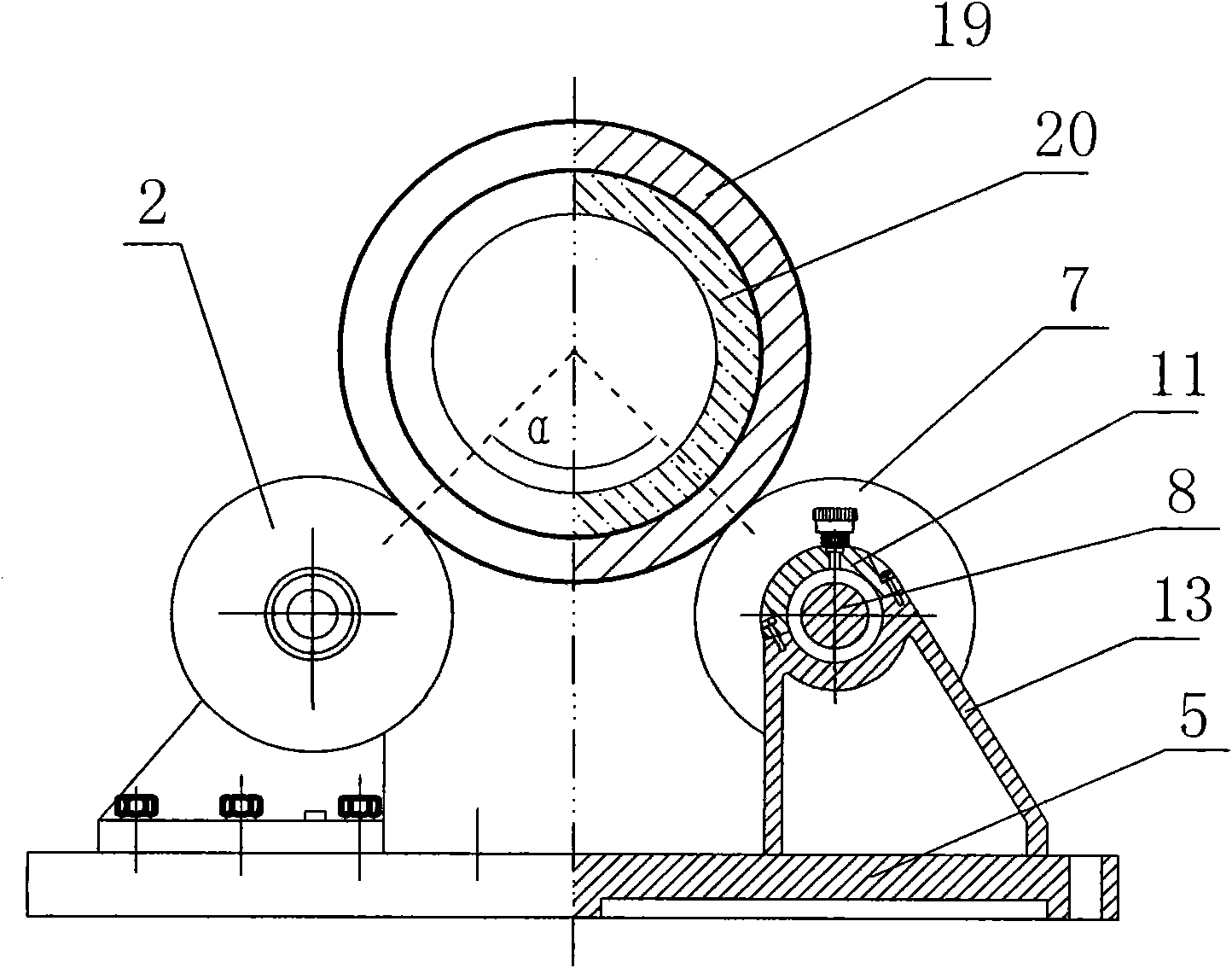
[0026] See Figure 1 to Figure 3 , The rolling centrifugal casting machine of the present invention includes a base 5 made of cast iron. The base 5 is provided with a plurality of anchor bolt holes 1 for fixing on the ground by anchor bolts. The base 5 is provided with a first support 9a and a second support 9b for supporting the shaft oppositely. The first support 9a and the second support 9b are respectively fixedly connected to the base 5 by bolts 12, and the base 5 There is also an adjustment screw hole 4 for adjusting the position of the second support, and the position of the second support 9b can be adjusted according to the diameter of the cylindrical mold 19 and fixed with bolts. A rotating shaft extending horizontally is provided on each of the two supports. The first support 9a is the driving shaft 8, and the second support 9b is the driven shaft 3. The two shafts are parallel and have the same horizontal height. The main and driven rotating shafts are respectively ...


PUM

PropertyMeasurementUnit
Angleaaaaaaaaaa

Abstract

The invention relates to a rolling type centrifugal casting machine. A first supporting seat and a second supporting seat which are used for supporting shafts are oppositely arranged on a base; a rotating shaft which extends horizontally is arranged on each of the two supporting seats; the two rotating shafts are parallel, and the heights of the two rotating shafts in the horizontal position are same; the rotating shafts are supported on the supporting seats through bearings; rollers for holding a cylinder casting mold for rotating are respectively installed at two extending ends of the rotating shaft; a driven wheel for receiving power transmission is installed at one end of the rotating shaft on the first supporting seat so as to enable the roller on the first supporting seat to be an active roller, and the roller on the second supporting seat to be a driven roller; and the spacing distance between the active roller and the driven roller is greater than the radius of the cylinder casting mold and is less than the diameter of the cylinder casting mold, thereby forming a raceway for the cylinder casting mold to rotate. The invention can enable the cylinder casting mold of which the axial length is greater than 400mm to be held by the rollers on the two supporting seats for rotating, overcomes the rotary swing of a cantilever type casting mold, realizes the purpose of carrying out centrifugal casting by using a longer cylinder casting mold, improves the production efficiency, has simple structure, and reduces the manufacturing cost of the centrifugal casting machine.

Description

Technical field [0001] The invention relates to a centrifugal casting equipment, in particular to a supporting roller centrifugal casting machine. Background technique [0002] see Figure 4 As shown, the existing centrifugal casting machine is usually a horizontal cantilever centrifugal casting machine. This kind of centrifugal casting machine has a complicated structure. In particular, one end of the casting mold 11 is connected to the shaft end of the main shaft 12 to form a cantilever state, and the rotation of the casting mold is driven by the rotation of the main shaft. The molten metal injected into the mold is casted under the action of centrifugal force. This cantilever centrifuge is cantilever-shaped because the mold is installed on the main shaft. In order to prevent the hanging end of the mold from rotating with the main shaft, it will affect the molding of the casting. The axial length of the mold is relatively short, generally not more than 400mm. It is used to inst...

Claims


Application Information

Patent Timeline
IPC IPC(8): B22D13/02
Inventor 刘伟刘诗雄
Owner 武胜县锦雄机械有限责任公司
Learn More