
Vaginal dilator with double side wings

A vaginal dilation and flank technology, applied in dilators, obstetrics and gynecology instruments, operations, etc., can solve the problems of patient pain, inability to recover, dilate the vaginal wall, etc., and achieve the effect of reducing pain, simple structure, and wide field of view.

Inactive Publication Date: 2010-10-27
江苏奥博金医药科技有限公司
View PDF9 Cites 27 Cited by
  • Summary
  • Abstract
  • Description
  • Claims
  • Application Information

AI Technical Summary

Problems solved by technology

But the defect of first three patents is that side lobe is all arranged on the outside of upper and lower wing and all can not reclaim in upper and lower wing, therefore can bring pain to patient when entering vagina; Though the 4th patent is to a certain extent Make up for the defects of the first three patents, set a side leaf in the lower wing, but its own defect is that there is only one side wing, and when used, it only plays the role of blocking the vaginal wall rather than expanding the vaginal wall
[0005] On the other hand, in the field of obstetrics and gynecology, due to the use of LEEP knife, also known as ultra-high frequency radio wave knife, harmful smoke with pungent throat and bad smell will be produced during the operation, which will affect the health of doctors and patients, and also affect the health of doctors and patients. blurred the doctor's vision
[0006] Chinese patent 200810107219.6 discloses a "disposable smoke-exhausting double-wing vaginal dilator and its manufacturing method". According to the patent, the vaginal dilator includes two expansion blades, upper and lower. The smoke pipe connected to the device has a defect that only one smoke pipe is installed on the upper wing, and the smoke inlet of the smoke pipe is set at the top of the pipe, which is not conducive to the discharge of smoke

Method used


Image

  • Vaginal dilator with double side wings
  • Vaginal dilator with double side wings
  • Vaginal dilator with double side wings

Examples


Embodiment Construction

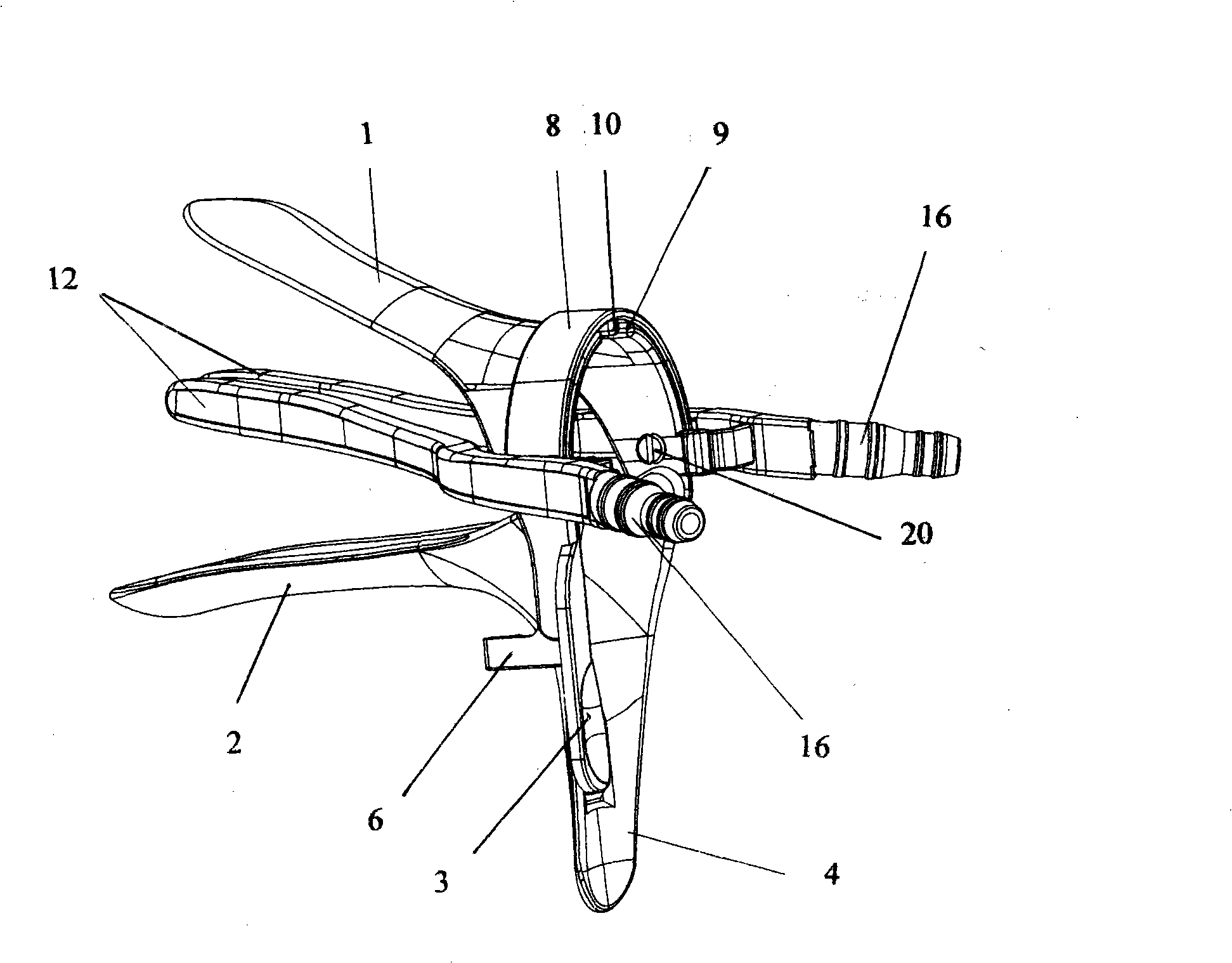
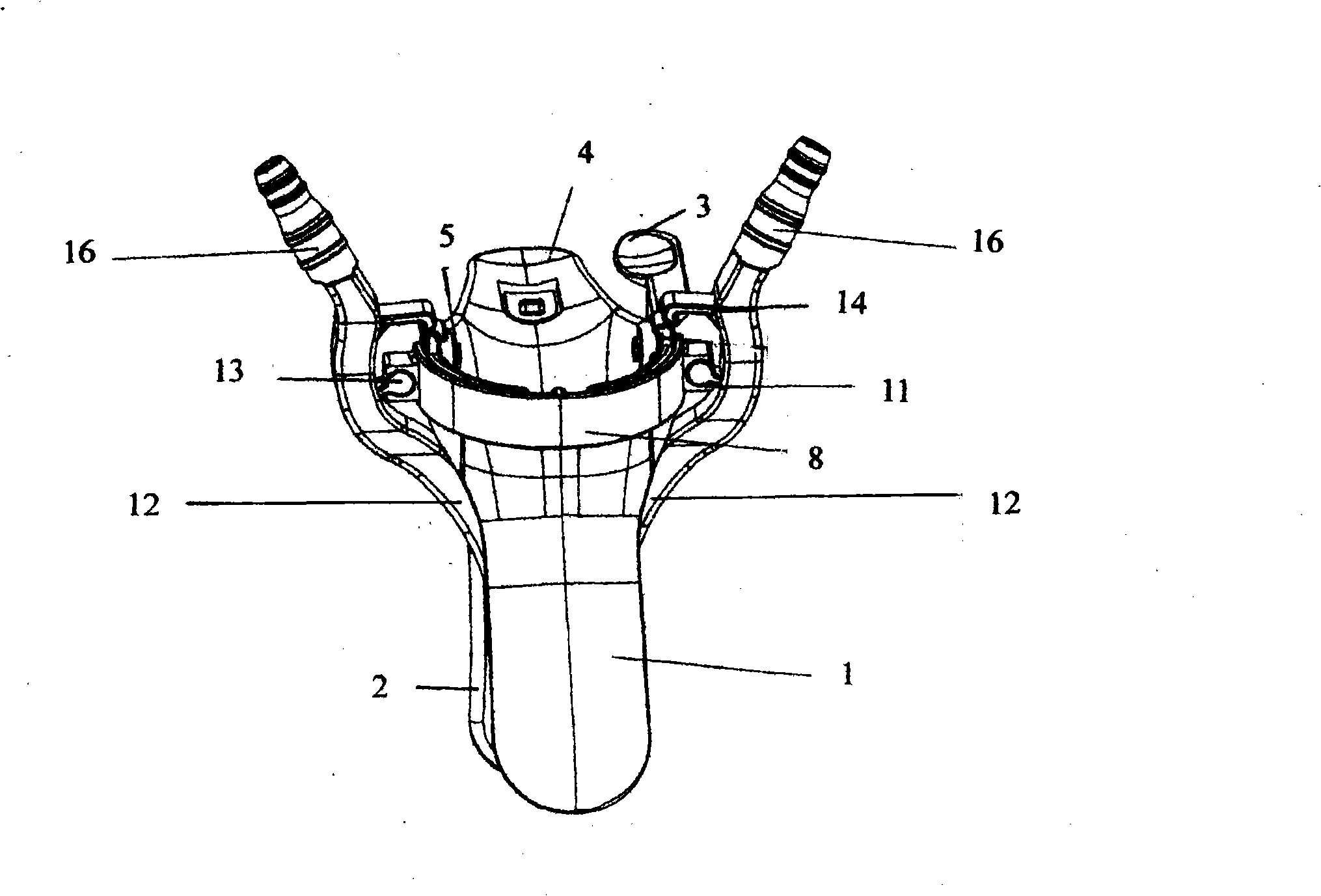
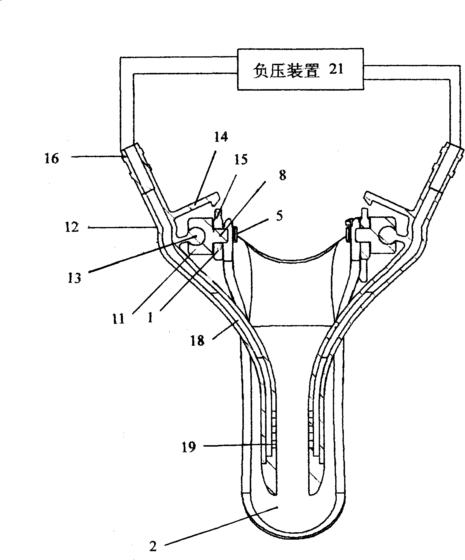
[0021] Attached below picture A vaginal dilator with double wings according to the present invention will be described. first refer to attached figure 1- 2. The vaginal dilator with double wings includes an upper wing 1, a handle 3 integral with the upper wing 1 and extending downward along one side of the upper wing at an obtuse angle, a lower wing 2, and a lower wing 2. The wing 2 is integrated, and the handle 4 extending downward along the lower wing 2 is close to a right angle to it. The two sides of the rear end of the upper wing 1 and the lower wing 2 are connected by pins 5 respectively. It can be closed by pressing the handle 3 times.

[0022] A first expanding and fixing device for fixing the opened state of the upper wing 1 and the lower wing 2, the device further includes a figure 1 The positioning hook plate 6 extending in the left direction is shown, the positioning hook is on the inner side of the plate 6, and a positioning buckle (not shown) corresponding t...


PUM


Abstract

The invention provides a vaginal dilator with double side wings, comprising an upper wing, a pressing handle, a lower wing, and a handle; the upper wing and the lower wing are connected through a pin; the pressing handle and the handle are meshed with each other through a first dilation fixing structure; the vaginal dilator further comprises an arc flexible locating sleeve rotatably connected with the upper wing; both ends of the sleeve are respectively provided with a mounting base; the base is provided with a mounting hole for holding the side wings capable of being held between the upper and the lower wings; the rear part of the side wings is provided with a second dilation fixing device meshed with the upper part of the rear end of the upper wing; and a passage can be installed in the side wing. Compared with the prior art, the vaginal dilator with double side wings has the advantages of wider field range, simple structure and easy manufacturing.

Description

technical field [0001] The invention relates to a vaginal dilator, in particular to a vaginal dilator with double side wings. Background technique [0002] Vaginal dilators are commonly used examination and surgical instruments in gynecology. Used to expose the inspection site or surgical site. Commonly used vaginal dilators include duckbill-shaped upper and lower wings that can be opened and closed. The positioning device on the dilator keeps the upper and lower wings open at a certain angle, and the doctor can see through the upper and lower wings. Observation, examination and surgery. In fact, limited by the width of the upper and lower wings themselves, and after the upper and lower wings are opened, the vaginal wall between the two sides of the upper and lower wings will be backfilled into the opened area, thereby reducing the exposure range, Difficulty in examination or surgery. If the opening angle of the upper and lower wings is increased, in addition to causing ...

Claims


Application Information

Patent Timeline
IPC IPC(8): A61M29/00A61B1/32A61B17/42
Inventor 林静张星星吴茜茜
Owner 江苏奥博金医药科技有限公司
Learn More