
New quick detection method for relay protective device

A technology of relay protection device and detection method, which is applied in the direction of measuring device, measuring electricity, measuring electrical variable, etc., to achieve the effect of reducing product cost, high speed, and reducing performance requirements

Active Publication Date: 2010-10-20
ELECTRIC POWER RESEARCH INSTITUTE OF STATE GRID SHANDONG ELECTRIC POWER COMPANY +1
View PDF4 Cites 11 Cited by
  • Summary
  • Abstract
  • Description
  • Claims
  • Application Information

AI Technical Summary

Problems solved by technology

However, the price of DSP is several times or even ten times higher than that of ordinary MCU. Not only the hardware cost is high, but also the development cycle is long and the circuit is complicated.

Method used


Image

  • New quick detection method for relay protective device
  • New quick detection method for relay protective device
  • New quick detection method for relay protective device

Examples


Embodiment Construction

[0036] Below in conjunction with accompanying drawing and embodiment the utility model is further described:

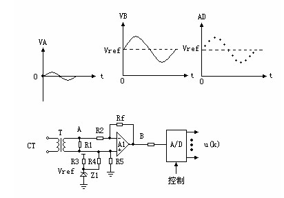
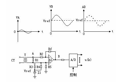
[0037] like figure 1 As shown, CT represents the current transformer, T represents the measurement transformer, R1 is the secondary load of T, the voltage VA generated by the current flowing through CT at point A is a small sine wave around zero potential (the waveform above point A) , the reference voltage Vref formed by R3 and Zener voltage regulator Z1 raises the potential of the small sine wave to Vref as a whole, and then the amplifier A1 amplifies the waveform into the form of point B (the VB waveform above), and the A / D conversion is The MCU is realized according to the sampling cycle timing, the output u(k) of the A / D becomes the binary digital quantity in the MCU, and u(k) is the discrete sampling point (k=1,2,…,N) (as shown by the above A discontinuous sinogram made of star points).

[0038] To obtain the magnitude and phase of electrical parameters fro...


PUM


Abstract

The invention discloses a new quick detection method for a relay protective device, which comprises the following steps of: acquiring an analog voltage signal first by utilizing a voltage or current transformer; performing level raising and signal amplification on the analog voltage signal and making the analog voltage signal enter an A / D converter; sampling the voltage signal for 4 times per cycle by using the A / D converter under the control of a microprocessor; separating a real part and an imaginary part of the signal from a sampled digital signal by utilizing an optimum least squares filter; and obtaining a quadratic sum of the real part and the imaginary part, and performing integer root solving by using a two-stage method to obtain an amplitude value and a phase of the analog signal. In the new quick detection method, the optimum least squares filter is combined with the integer root solving by the two-stage method, so the key calculation problem in the protection and measurement of a relay is solved, and simultaneously, the calculation speed is higher; and the optimum filter for sampling four points per cycle and the integer root solving reduce the requirement on the performance of CPUs (MCUs or DSPs) greatly.

Description

technical field [0001] The invention relates to a new rapid detection method of a relay protection device. Background technique [0002] At present, with the development of electronic technology, relay protection has been fully digitized. The electrical signal from the voltage or current transformer enters the A / D converter after the level is raised and the signal is amplified, and is sampled at a certain period under the control of the microprocessor (MCU) or digital processor (DSP). [0003] After the MCU or DSP realizes the rapid sampling of the electrical signal, the next step of calculation and judgment is performed. If the value is too large, the circuit breaker is driven through the output relay to cut off the faulty line or equipment. Among them, identifying the amplitude and phase of the electrical signal from the AC discrete sampling signal is the basis and key of the entire protection. The amplitude and phase determine all the characteristics of an electrical f...

Claims


Application Information

Patent Timeline
Patent Type & Authority Applications(China)
IPC IPC(8): G01R31/00G01R25/00G01R19/25
Inventor 丁卫东
Owner ELECTRIC POWER RESEARCH INSTITUTE OF STATE GRID SHANDONG ELECTRIC POWER COMPANY
Learn More