Double clutch transmission

A dual-clutch and transmission technology, applied in the direction of vehicle gearbox, transmission, transportation and packaging, can solve the problem of lengthening the structure and achieve the effect of small construction space requirements

Inactive Publication Date: 2010-10-20
ZF FRIEDRICHSHAFEN AG
View PDF8 Cites 0 Cited by
  • Summary
  • Abstract
  • Description
  • Claims
  • Application Information

AI Technical Summary

Problems solved by technology

This leads to an undesired extension of the construction length in the axial direction

Method used


Image

  • Double clutch transmission
  • Double clutch transmission
  • Double clutch transmission

Examples


Embodiment Construction

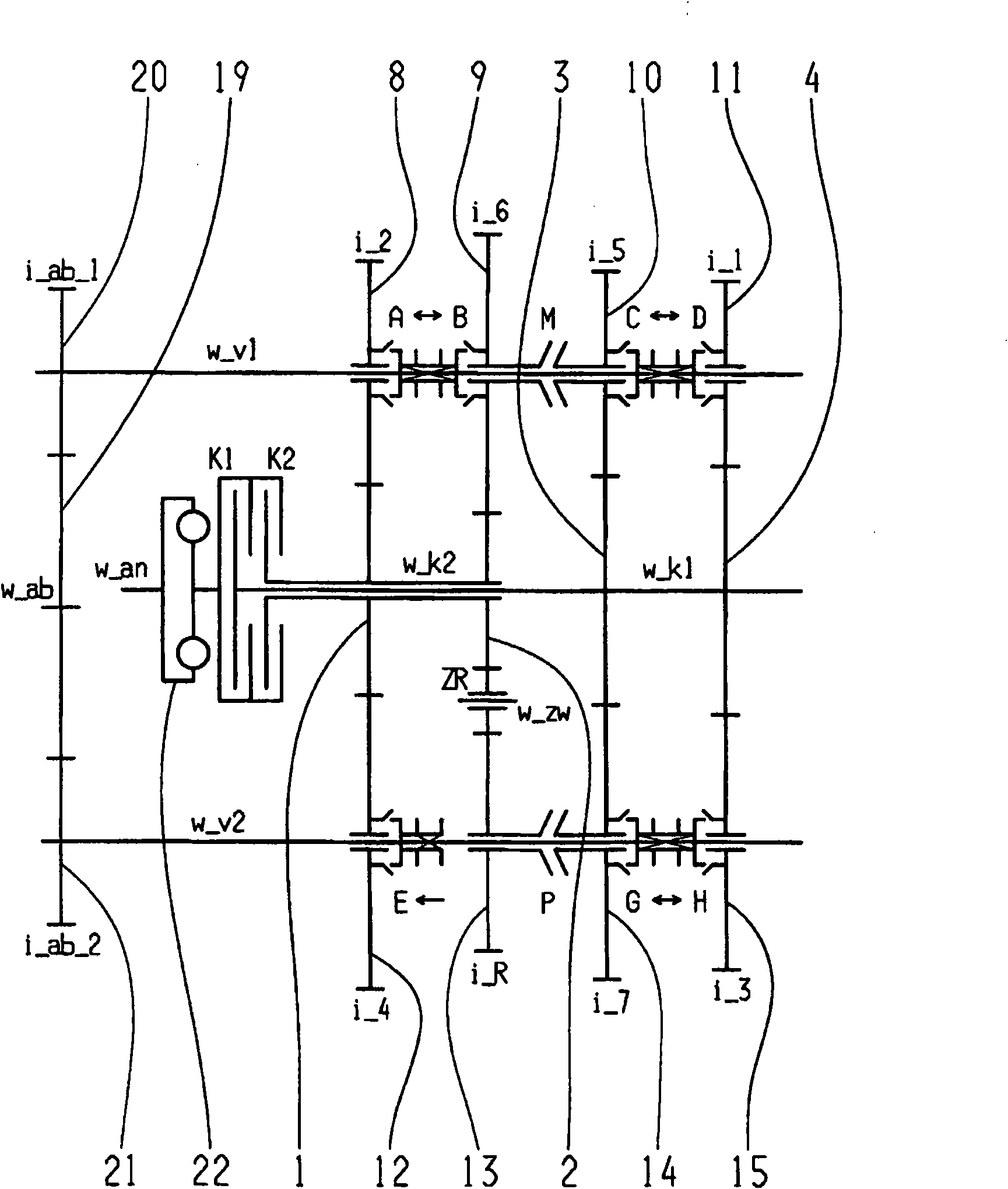
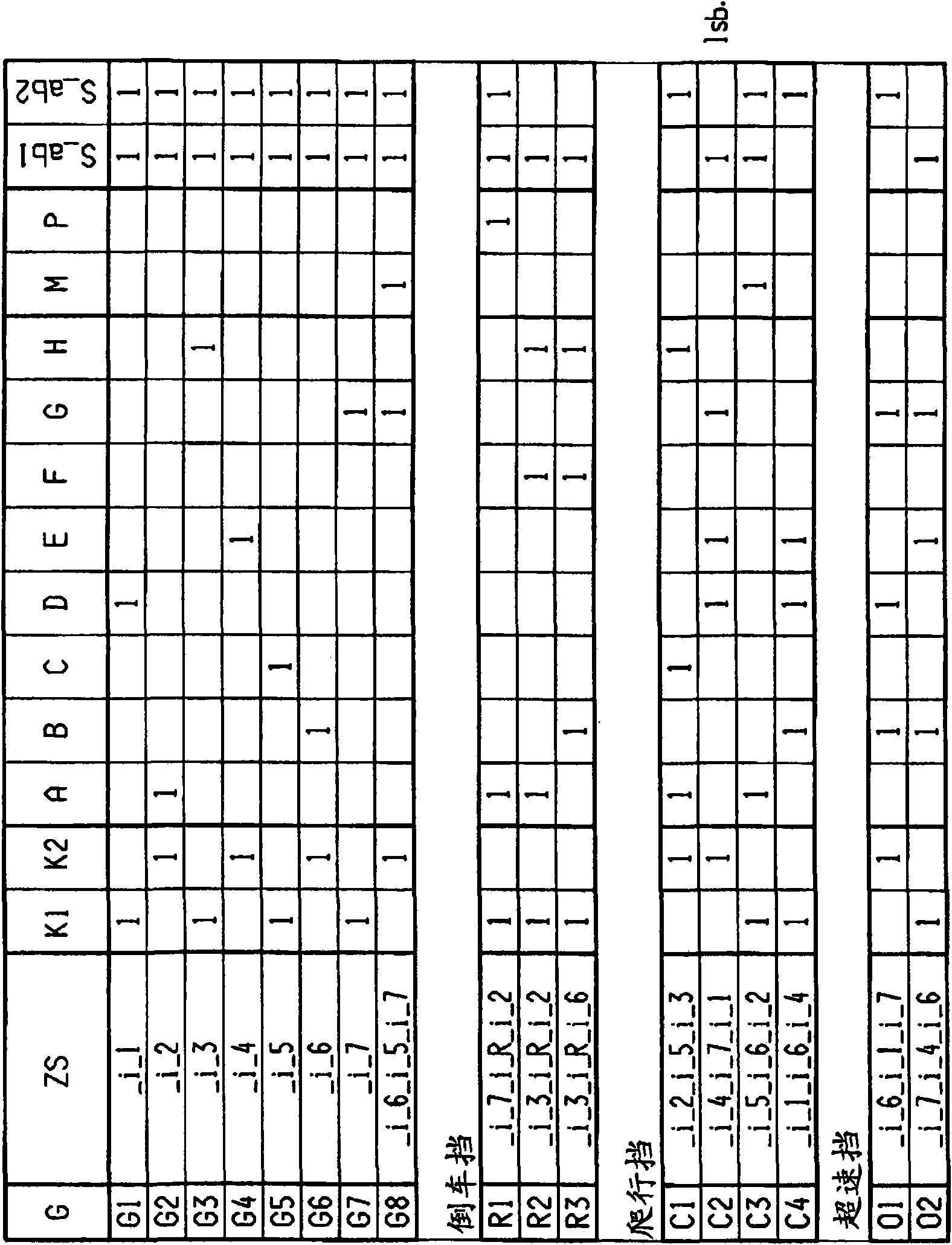
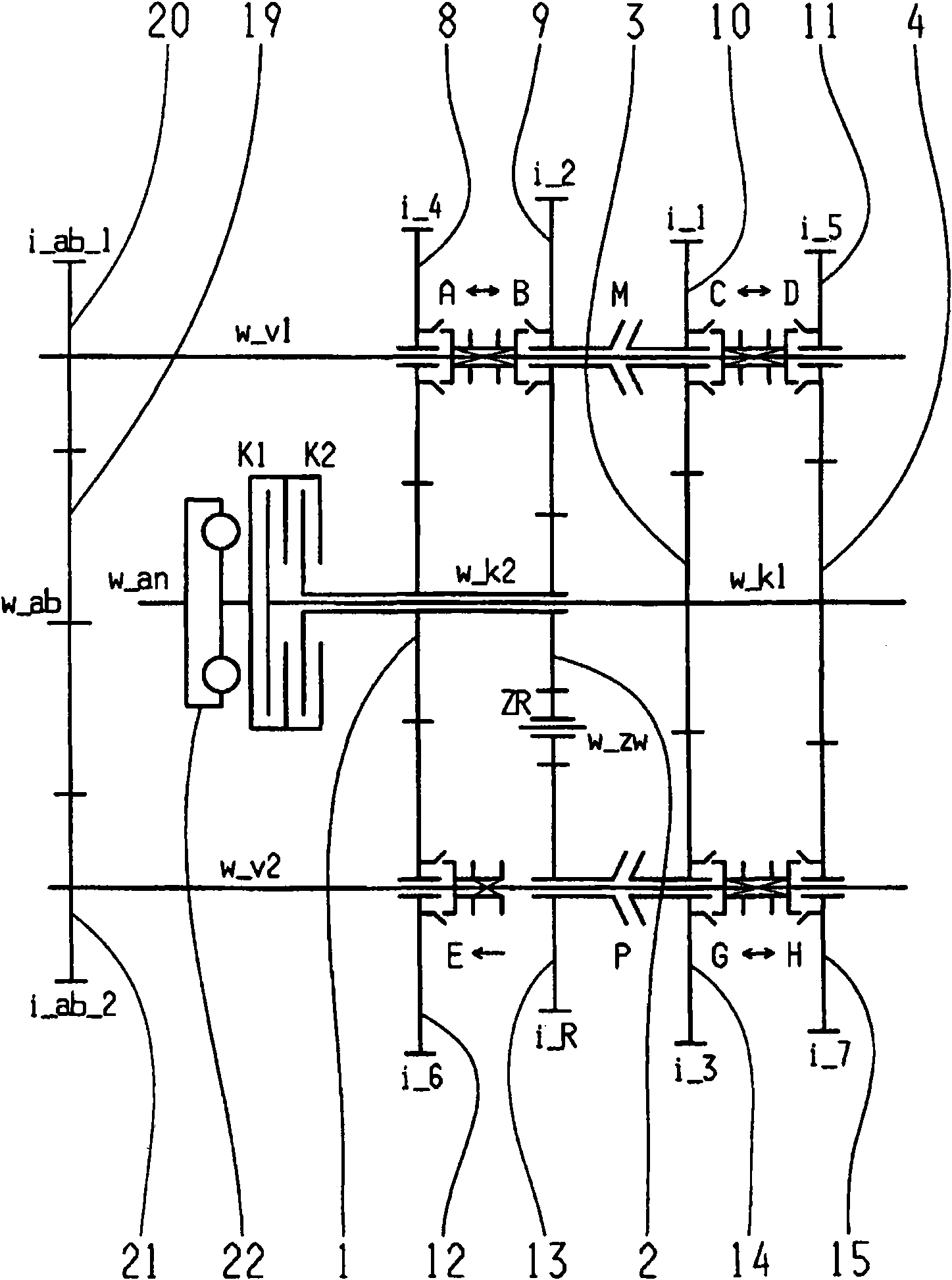
[0046] exist figure 1 , 3 , 5, 7, 9 and 11 respectively show a possible implementation of an eight-speed dual-clutch transmission. figure 2 , 4 , 6, 8, 10 and 12 show the corresponding shift diagrams for various embodiments in tabular form.

[0047] The eight-speed dual-clutch transmission comprises two clutches K1, K2, the inputs of which are connected to a drive shaft w_an and the outputs of which are each connected to one of the two coaxially arranged transmission input shafts w_k1, w_k2 connected. Furthermore, a torsional vibration damper 22 can be arranged on the drive shaft w_an. Furthermore, two countershafts w_v1 , w_v2 are provided, on which gearwheels formed as idler gearwheels 7 , 8 , 9 , 10 , 11 , 12 , 13 , 14 , 15 , 16 , 17 are rotatably mounted. On the two transmission input shafts w_k1, w_k2, the gear gears configured as fixed gears 1, 2, 3, 4, 5 are fixedly rotated and arranged, which are at least partially connected with the idler gears 7, 8, 9, 10, 11, ...


PUM


Abstract

A double clutch transmission comprising two clutches (K1, K2) the input sides of which are each connected to a drive shaft (w_an) and the output sides of which are respectively connected to one of two coaxially disposed transmission input shafts (w_k1, w_k2). Toothed idler gearwheels (8, 9, 10, 11, 12, 13, 14, 15) are mounted on the two countershafts (w_v1, w_v2) while toothed fixed gearwheels (1, 2, 3, 4) are provided on the two transmission input shafts (w_k1, w_k2) whereby several power shiftable forward gears (1, 2, 3, 4, 5, 6, 7, 8) and at least one reverse gear (R1, R2, R3) are shiftable. A maximum of five gear planes (8-12, 9-13, 10-14, 11-15) are provided so that at least one power shiftable winding path gear (G8, C3) is shifted by the shift element (M) and at least one power shiftable winding path gear (R1) is shifted by the shift element (P).

Description

technical field [0001] The invention relates to a dual clutch transmission for a motor vehicle of the type specified in the preamble of claim 1 . Background technique [0002] A six-speed or seven-speed dual clutch transmission is known from laid-open publication DE 103 05 241 A1. The dual-clutch transmission includes two clutches, each of which is connected with its input to a drive shaft and with its output to one of the two transmission input shafts. The two transmission input shafts are arranged coaxially with one another. Furthermore, two countershafts are arranged parallel to the axes of the two transmission input shafts, the idler gears of which mesh with the fixed gears of the respective transmission input shafts. Furthermore, a plurality of axially displaceable coupling devices are held rotationally fixed on the countershafts in order to be able to engage the corresponding gearwheels. The correspondingly selected transmission ratio is transmitted via the output g...

Claims


Application Information

Patent Timeline
Patent Type & Authority Applications(China)
IPC IPC(8): F16H3/093
CPCF16H2003/0931F16H2003/0826F16H2200/0091F16H2200/0026F16H3/006F16H2200/0086F16H2200/006F16H2200/0065F16H2200/0095Y10T74/19228
Inventor W·里格尔M·赖施J·瓦夫齐希P·雷克G·贡波尔茨贝格
Owner ZF FRIEDRICHSHAFEN AG
Why Eureka
Try Eureka