Optical connection structure
An optical connection and optical ground technology, applied in the directions of optics, optical components, light guides, etc., can solve the problems of damage to the front end of the optical fiber and the end face of the waveguide, unable to realize the optical connection structure, unable to retract the optical fiber holding groove, etc. The effect of saving space and reducing man-hours for manufacturing
- Summary
- Abstract
- Description
- Claims
- Application Information
AI Technical Summary
Problems solved by technology
Method used
Image
Examples
Embodiment 1
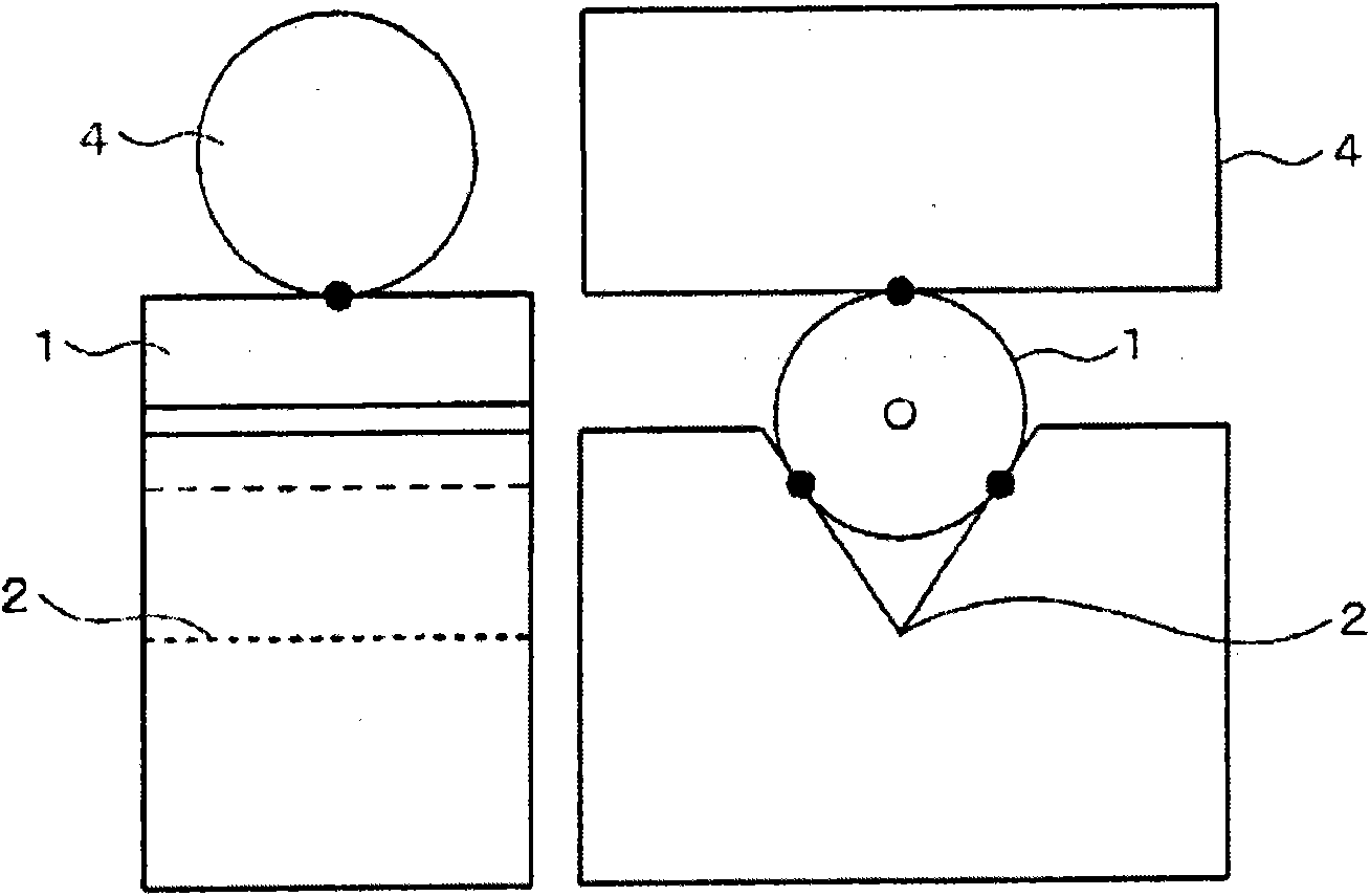
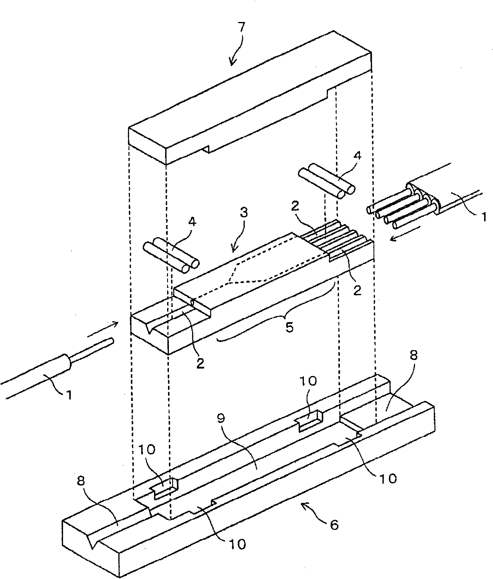
[0120] On one side of a 4 x 40mm PEEK (polyetheretherketone) package made of 4 x 4 x 40mm, optical fiber accommodation grooves with a width of 1.1 mm x length 10 mm x a depth of 2 mm are sequentially provided in series on one side of the 4 x 40 mm, width 1.5 mm x length 20.0 mm × depth 3mm optical waveguide accommodation groove with V-groove and optical fiber accommodation groove width 0.3mm × length 10mm × depth 2mm. Next, a groove for retracting the pressing body with a width of 1.5 mm×length 3 mm×a depth of 2 mm is provided so that when the optical waveguide with a V-groove is housed in the groove for retracting an optical waveguide with a V-groove, the V-groove is placed on the V-groove. The upper surface of the V-groove region which is perpendicular to the V-groove and has the V-groove optical waveguide becomes the bottom surface of the pressing body storage groove.
[0121] Next, a 2-branch optical waveguide in which a V-groove with a length of 2 mm was integrated was in...
Embodiment 2
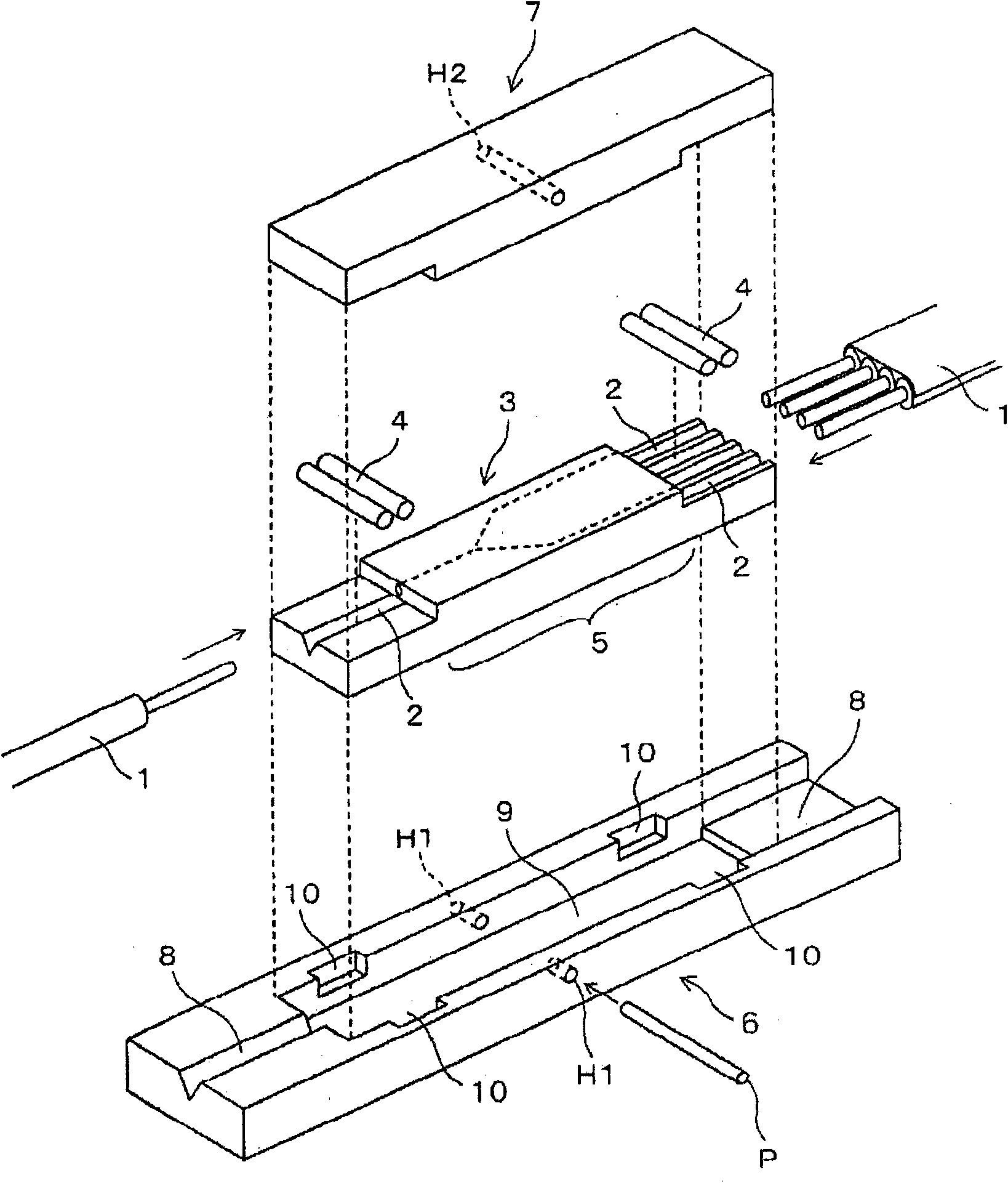
[0125] In the optical connection structure of the above-mentioned embodiment 1, a through hole H1 with a diameter of 0.7 mm is provided in the center of the packaging component, a through hole H2 with a diameter of 0.75 mm is provided in the center of the pressing body support component, and the packaging component, the optical waveguide, and the pressing body are assembled in advance. body and the pressing body support member, and then insert a stainless steel support rod with a length of 4mm and a diameter of 0.7mm into the through hole H1 and the through hole H2, and integrate the optical connection structure. 2 optical connection structure.
Embodiment 3
[0127] The dimensions of the V-groove optical waveguide substrate storage groove and the optical fiber storage groove are 0.9 mm in width x 8.2 mm in length x 2.0 mm in depth and 0.5 mm in width x 15.9 mm in length x 1.8 mm in depth. Groove optical waveguide, pressing body, and optical fiber, and after clamping the pressing body support member and the bottom surface of the package member with a clip-shaped member, the optical fiber is not bonded with an adhesive, but matching oil is dripped on the end of the optical waveguide, Except for this, in the same manner as in Example 2, the optical connection structure of Example 3 was produced.
[0128] As an optical waveguide with V-groove, a Figure 28 2-branch beam splitter shown. The beam splitter is designed to have a low loss of less than 1dB on the 1 channel side ( Figure 28 port on the upper right), and the 2-channel side is for monitoring ( Figure 28 The lower right mouth) indicates a large loss of about 45dB. As press...
PUM
 Abstract
Description
Claims
Application Information
 - Generate Ideas
- Intellectual Property
- Life Sciences
- Materials
- Tech Scout
- Unparalleled Data Quality
- Higher Quality Content
- 60% Fewer Hallucinations
Browse by: Latest US Patents, China's latest patents, Technical Efficacy Thesaurus, Application Domain, Technology Topic, Popular Technical Reports.
© 2025 PatSnap. All rights reserved.Legal|Privacy policy|Modern Slavery Act Transparency Statement|Sitemap|About US| Contact US: help@patsnap.com


