
Signal demodulation method

A signal demodulation and signal technology, applied in the field of signal demodulation, can solve the problems of large hardware resource occupation, slow frequency drift of received data signals, system performance degradation, etc., achieve the effect of ensuring the occupation of hardware resources and reducing the complexity of algorithms

Inactive Publication Date: 2010-10-13
湖北众友科技实业股份有限公司
View PDF3 Cites 4 Cited by
  • Summary
  • Abstract
  • Description
  • Claims
  • Application Information

AI Technical Summary

Problems solved by technology

[0004] However, after removing ISI and MAI interference through channel estimation and joint detection, there is still a linear deviation in the signal, which is the phase deviation caused by the frequency error
Due to the influence of Doppler frequency shift and local carrier error, the received data signal will have a slow frequency drift, which will cause the phase drift of the received data signal, which will have a bad impact on the communication system and degrade the system performance
Existing methods for eliminating frequency offset are very complicated, require a large amount of calculation and occupy a large amount of hardware resources

Method used


Image

  • Signal demodulation method
  • Signal demodulation method
  • Signal demodulation method

Examples


Embodiment Construction

[0021] Embodiments of the present invention will now be described with reference to the drawings, in which like reference numerals represent like elements. As mentioned above, the present invention provides a signal demodulation method with low algorithm complexity, less hardware resource occupation and effective guarantee of demodulation performance.

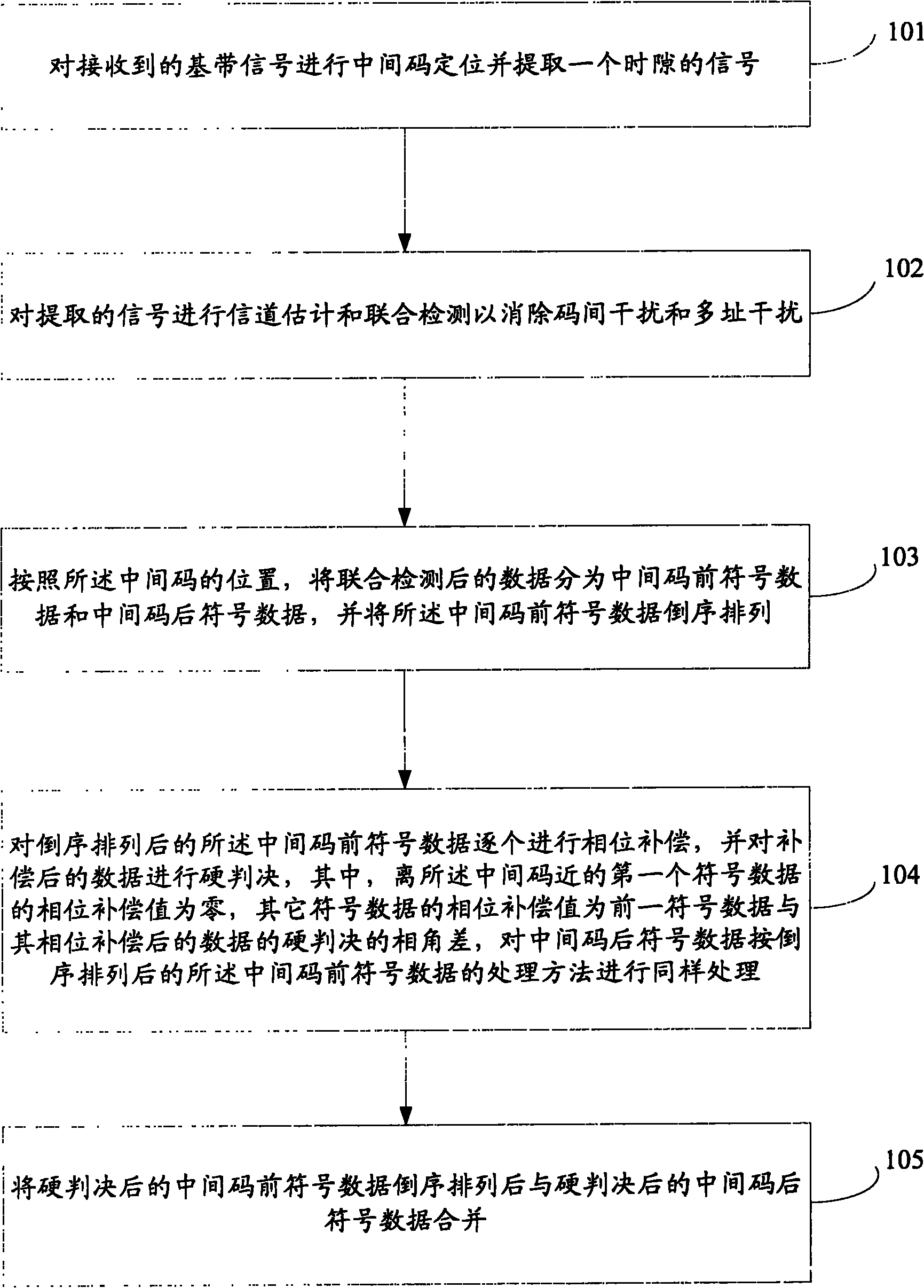
[0022] The technical solutions of the embodiments of the present invention will be described in detail below in conjunction with the accompanying drawings. like figure 1 As shown, the signal demodulation method in this embodiment includes the following steps.

[0023] Step 101: Perform midamble positioning on the received baseband signal and extract a signal of one time slot.

[0024] Specifically, after the signal is received, the received signal is filtered, and the correlation calculation is performed on the I and Q signals to obtain the correlation peak value. According to the correlation peak value, the position of the m...


PUM


Abstract

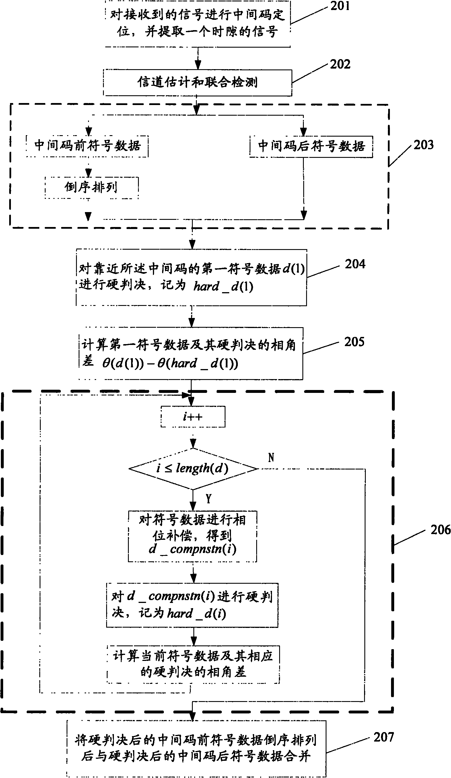
The invention discloses a signal demodulation method, which comprises the following steps of: positioning an intermediate code of a signal and extracting a signal of one time slot; carrying out channel estimation and joint detection on the extracted signal; and carrying out hard decision on data subjected to joint detection. The hard decision step particularly comprises the following steps of: dividing the data into symbol data in front of the intermediate code and symbol data behind the intermediate code according to the position of the intermediate code and carrying out reverse order arrangement on the symbol data in front of the intermediate code; carrying out phase compensation on the symbol data in front of the intermediate code, which is subjected to reverse order arrangement, one by one and carrying out hard decision on the compensated data, wherein a phase compensation value of first symbol data closest to the intermediate code is zero and phase compensation values of other data are respectively a phase-angle difference of the hard decision of previous symbol data and data obtained after the previous symbol data is subjected to phase compensation; carrying out the same treatment on the symbol data behind the intermediate code according to the treatment method of the symbol data in front of the intermediate code, which is subjected to reverse order arrangement; after carrying out reverse order arrangement on the symbol data in front of the intermediate code, combining the symbol data in front of the intermediate code, which is subjected to hard decision, with the symbol data behind the intermediate code, which is subjected to hard decision.

Description

technical field [0001] The invention relates to the field of communication technology, in particular to a signal demodulation method. Background technique [0002] In 3G (Third Generation, third generation) and B3G (Beyond Third Generation, super third generation) mobile communication systems, the coding technology uses QPSK (Quadrature Phase Shift Keying, quadrature phase shift keying), 16QAM ( QuadratureAmplitude Modulation, quadrature amplitude modulation) modulation method. Due to the existence of ISI (Inter-Singnals Interference, inter-symbol interference), MAI (Multi-Access Interference, multiple access interference) and frequency error (such as Doppler effect, the frequency error is not up to standard during the test) and other interference between signals , the performance of the communication system is limited. [0003] In order to improve the performance of the communication system, channel estimation and joint detection techniques are used to eliminate the ISI a...

Claims


Application Information

Patent Timeline
IPC IPC(8): H04L27/38H04L25/03H04L25/02H04B1/707
Inventor 曾志雄朱富利王波郑敏江刘焱骊
Owner 湖北众友科技实业股份有限公司
Learn More