
Display filter for LCD having anti-fog layer

A filter and display technology, applied in instruments, coatings, optics, etc., can solve problems such as difficulty in removing fog, blurring, etc., and achieve the effect of reducing eye fatigue

Inactive Publication Date: 2010-10-13
SAMSUNG CORNING CO LTD
View PDF4 Cites 2 Cited by
  • Summary
  • Abstract
  • Description
  • Claims
  • Application Information

AI Technical Summary

Problems solved by technology

However, since the LCD module emits only a small amount of heat, LCDs are fundamentally difficult to remove fog (blurring)

Method used


Image

  • Display filter for LCD having anti-fog layer
  • Display filter for LCD having anti-fog layer
  • Display filter for LCD having anti-fog layer

Examples


Embodiment Construction

[0022] Reference will now be made in detail to various embodiments of the invention, examples of which are illustrated in the accompanying drawings and described below. While the invention has been described in conjunction with exemplary embodiments, it is to be understood that present description is not intended to limit the invention to those exemplary embodiments. On the contrary, the invention is intended to cover not only the exemplary embodiments, but also various alterations, modifications, equivalents and other embodiments, which may be included within the spirit and scope of the invention as defined by the appended claims.

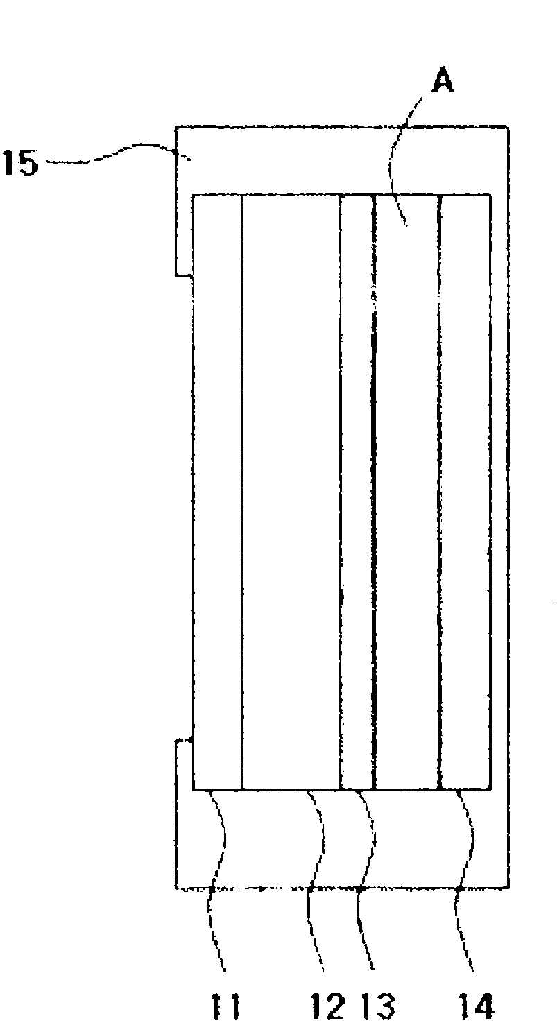
[0023] figure 1 is a schematic diagram showing the structure of an LCD using a display filter according to an exemplary embodiment of the present invention.

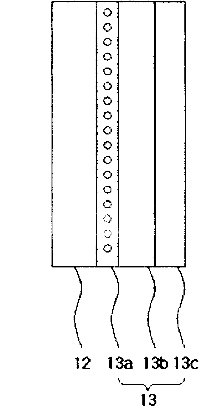
[0024] As shown in the figure, an LCD generally includes an anti-reflection film 11 , a transparent support 12 , an anti-fog layer 13 , a display module 14 and a housing 15 .

[0025] The ...


PUM

PropertyMeasurementUnit
compressive strengthaaaaaaaaaa
diameteraaaaaaaaaa
refractive indexaaaaaaaaaa

Abstract

A display filter for a Liquid Crystal Display (LCD) having an anti-fog function includes a transparent support arranged in front of the display module and an anti-fog layer stacked in the rear of the transparent support to face the display module. The anti-fog layer prevents the display filter from fogging up.

Description

[0001] Cross References to Related Applications [0002] This application claims priority and benefit from Korean Patent Application No. 10-2009-0028082 filed Apr. 1, 2009, the entire contents of which are hereby incorporated by reference. technical field [0003] The present invention relates to a display filter. More particularly, the present invention relates to a display filter for a liquid crystal display (LCD) having an anti-fog function. Background technique [0004] With the development of display technology, various flat panel display devices are available in the market. The most prominent display devices are LCD devices (used as monitors and televisions) and plasma display panel (PDP) devices. Currently, PDPs and LCDs are competing fiercely with each other because they have different advantages and disadvantages in many aspects. [0005] In terms of image quality, the colors produced by a PDP look more natural and smooth than those produced by an LCD. However, ...

Claims


Application Information

Patent Timeline
Patent Type & Authority Applications(China)
IPC IPC(8): G02F1/1335G02B1/10G02B1/11
CPCG02B27/0006G02F2201/50G02F1/1335G02B1/18G02B1/11
Inventor 申东根朴大出金信旭朴东炫李东活
Owner SAMSUNG CORNING CO LTD
Learn More