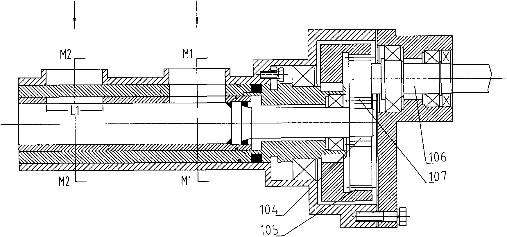
Air inlet sectioning device for internal combustion engine
A technology for internal combustion engines and intake pipes, applied in the field of intake systems, can solve problems such as reducing the service life of compressors, and achieve the effects of improving endurance, improving stability, and improving transient response speed
- Summary
- Abstract
- Description
- Claims
- Application Information
AI Technical Summary
Problems solved by technology
Method used
Image
Examples
Embodiment 1
[0034] Such as figure 1 , which is a segmented device for an intake port of an internal combustion engine, comprising one intake port 1-J, two intake pipes J1, J2; the outlet of the intake port 1-J is connected to the cylinder intake valve K1; The inlet of the intake pipe J1 is connected to the smoke exhaust pipe 20, and the inlet of the intake pipe J2 is connected to the air filter 10 (if the air is relatively clean, the intake pipe J2 can also be directly connected to the air); the intake duct 1-J is connected to two intake ducts There is one intake auxiliary control valve F1 between J1 and J2; the opening and closing of the intake auxiliary control valve F1 of the intake port 1-J corresponds to the phase of the gas distribution timing of the cylinder intake valve K1, so that The complete intake process of the intake channel 1-J is divided into two intake duration periods, and the corresponding intake channel 1-J is connected to the corresponding intake pipe during the two s...
Embodiment 2
[0041] Such as Image 6 , is an optimized air intake section device with 6 intake ports, including 6 intake ports 1-J, 2-J, 3-J, 4-J, 5-J, 6-J, 2 The intake pipes J1, J2; the internal combustion engine contains 6 intake valves; The air valve inlets K1, K2, K3, K4, K5, K6 are connected; the intake pipe J1 is connected with the air filter 10, and the intake pipe J2 is connected with the outlet 41 of the intercooler 40; 6 intake passages 1-J, Between 2-J, 3-J, 4-J, 5-J, 6-J and the 2 intake pipes J1, J2 are respectively provided with 2 intake auxiliary control valves F1, F2; 6 intake ducts 1- The opening and closing of the intake auxiliary control valves of J, 2-J, 3-J, 4-J, 5-J, and 6-J correspond to the timing phases of the intake valves connected to the 6 intake ports , so that the complete intake process of the six intake ports 1-J, 2-J, 3-J, 4-J, 5-J, and 6-J is divided into two intake durations, and the corresponding intake The air passage is connected with the correspon...
Embodiment 3
[0051] Such as Figure 11 , which is another optimized intake segment device with 6 intake ports, including 6 intake ports 1-J, 2-J, 3-J, 4-J, 5-J, 6-J, 2 Root intake pipe J1, J2, intercooler 40, centrifugal compressor 30; internal combustion engine contains 6 intake valves; 6 intake ports 1-J, 2-J, 3-J, 4-J, 5-J , 6-J are directly connected with the intake valve inlets K1, K2, K3, K4, K5, K6 of each single cylinder; the return hole 31 of the intake pipe J1 and the centrifugal compressor 30 (see the sectional view Figure 12 ), the intake pipe J2 is connected with the outlet 41 of the intercooler 40; the six intake passages 1-J, 2-J, 3-J, 4-J, 5-J, 6-J are connected with two intake pipes J1 There are two intake auxiliary control valves F1 and F2 respectively between the intake pipe J1 and J2; the flow control valve F10 is set at the part where the intake pipe J1 is connected to the return hole of the centrifugal compressor 30, and the flow rate is set between the intake pipe ...
PUM
 Abstract
Description
Claims
Application Information
 - R&D
- Intellectual Property
- Life Sciences
- Materials
- Tech Scout
- Unparalleled Data Quality
- Higher Quality Content
- 60% Fewer Hallucinations
Browse by: Latest US Patents, China's latest patents, Technical Efficacy Thesaurus, Application Domain, Technology Topic, Popular Technical Reports.
© 2025 PatSnap. All rights reserved.Legal|Privacy policy|Modern Slavery Act Transparency Statement|Sitemap|About US| Contact US: help@patsnap.com


