
Feeder

A feeder and pusher technology, which is applied to conveyor objects, transportation and packaging, etc., can solve the problems of affecting the quality of materials and the life of the heating furnace, low work efficiency, and high production costs, achieving the same heating time and reducing the use of manpower , the effect of reducing business costs

Inactive Publication Date: 2011-12-28
FIVE POWER ELECTRICAL TECHKUNSHAN
View PDF0 Cites 0 Cited by
  • Summary
  • Abstract
  • Description
  • Claims
  • Application Information

AI Technical Summary

Problems solved by technology

[0005] In order to solve the problem that the heating furnace adopts manual feeding in the prior art, the work efficiency is low, the production cost is high, and the problem of affecting the quality of the material and the life of the heating furnace is solved. The present invention provides a feeding machine for automatic feeding.

Method used


Image

  • Feeder
  • Feeder
  • Feeder

Examples


Embodiment Construction

[0017] The present invention will be further described below in conjunction with the accompanying drawings.

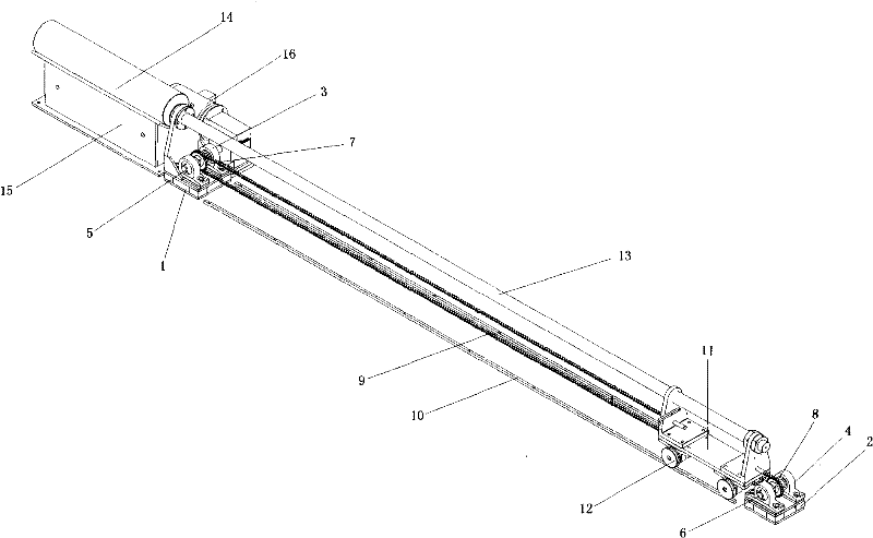
[0018] Such as figure 1 , 2 As shown in , 3, the feeder includes front end bearing frame 1 and rear end bearing frame 2, driving shaft 5, driven shaft 6, driving sprocket 7 and driven sprocket 8, conveying chain 9, slideway 10, cart 11. The long push shaft 13, the pusher head 14, the V-shaped groove 15, the motor 16 and the reducer are provided with a front end bearing frame 1 at the front end of the feeder, and a rear end bearing frame 2 at the rear end of the feeder. The two ends of the front end bearing frame 1 are provided with the front end bearings 3, the two ends of the rear end bearing frame 2 are provided with the rear end bearings 4, and the drive shaft 5 is arranged between the two front end bearings 3, and between the two rear end bearings 4 A driven shaft 6 is provided, a driving sprocket 7 is arranged on the driving shaft 5, a driven sprocket 8 is arran...


PUM


Abstract

The invention discloses a feeder, which is characterized in that bearing brackets are arranged at the two ends of the feeder; a V-shaped groove is arranged at the front side of the front bearing bracket; bearings are respectively arranged on the two bearing brackets; a driving shaft is arranged on the front bearing, and a driven shaft is arranged on the rear bearing; chain wheels are respectivelyarranged on the driving shaft and the driven shaft; the two chain wheels are connected through a delivery chain; a slide way is arranged at the bottom of the delivery chain; a cart is arranged on thedelivery chain; a guide wheel at the bottom of the cart is arranged on the slide way; a long thrust shaft is arranged on the top of the cart; the direction of the long thrust shaft is consistent withthe delivery direction of the delivery chain; and the front end of the long thrust shaft is connected with a material-pushing head, the lower side of the material-pushing head is arranged on the V-shaped groove, and a motor is connected with the driving shaft through a reducer. The automatic feeder provided by the invention solves the problems of low working efficiency, high production cost and influence on material quality and service life of the heating furnace which are caused by adopting manual feeding in a heating furnace in the prior art.

Description

technical field [0001] The invention relates to a feeder, in particular to a feeder for feeding materials to a heating furnace. Background technique [0002] The heating furnace is a commonly used mechanical equipment, and the heating furnace is a device for heating materials. According to the heat source, there are fuel heating furnaces, resistance heating furnaces, induction heating furnaces, microwave heating furnaces, etc. For example, in the extrusion production of copper ingots, a heating furnace is commonly used, which is to melt the remelted copper into a copper rod of about 6 meters to 8 meters, and then use a sawing machine to saw the copper rod into a small short rod, and then feed it manually Arrange and stack the short rods on the conveyor belt of the heating furnace, enter the furnace from the tail and heat them to the extrusion temperature, and finally the workers send the copper ingots into the extruder to extrude the profile, which is currently in great dem...

Claims


Application Information

Patent Timeline
Patent Type & Authority Patents(China)
IPC IPC(8): B65G47/82
Inventor 阙伯勋
Owner FIVE POWER ELECTRICAL TECHKUNSHAN
Learn More