Liquid crystal display device
A liquid crystal display device, liquid crystal cell technology, applied in the directions of instruments, polarizing elements, optics, etc., can solve the problem of not giving any suggestions, etc., and achieve the effects of less environmental dependence of optical performance, simple method, and reduced color shift
- Summary
- Abstract
- Description
- Claims
- Application Information
AI Technical Summary
Problems solved by technology
Method used
Image
Examples
Embodiment approach 1-1 and 1-2
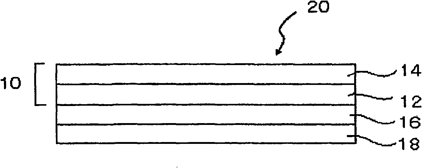
[0115] A VA (Vertical Alignment) liquid crystal display device according to Embodiment 1-1 of the present invention, comprising at least: a light source, a liquid crystal cell including a pair of substrates and a liquid crystal layer interposed between the substrates, and a film containing a thermoplastic resin composition , the thermoplastic resin composition contains a lactone ring-containing polymer. The film is arranged on the side of the liquid crystal cell closer to the light source. Regarding the film containing the thermoplastic resin composition containing a lactone ring-containing polymer, reference can be made to the description of "thermoplastic resin film containing a lactone ring-containing polymer" in the optical compensation sheet described later.
[0116] "The film is disposed on the light source side of the liquid crystal cell" means that when one or more film layers are provided on the light source side of the liquid crystal cell, the thermoplastic resin com...
Embodiment approach 2-1 and 2-2
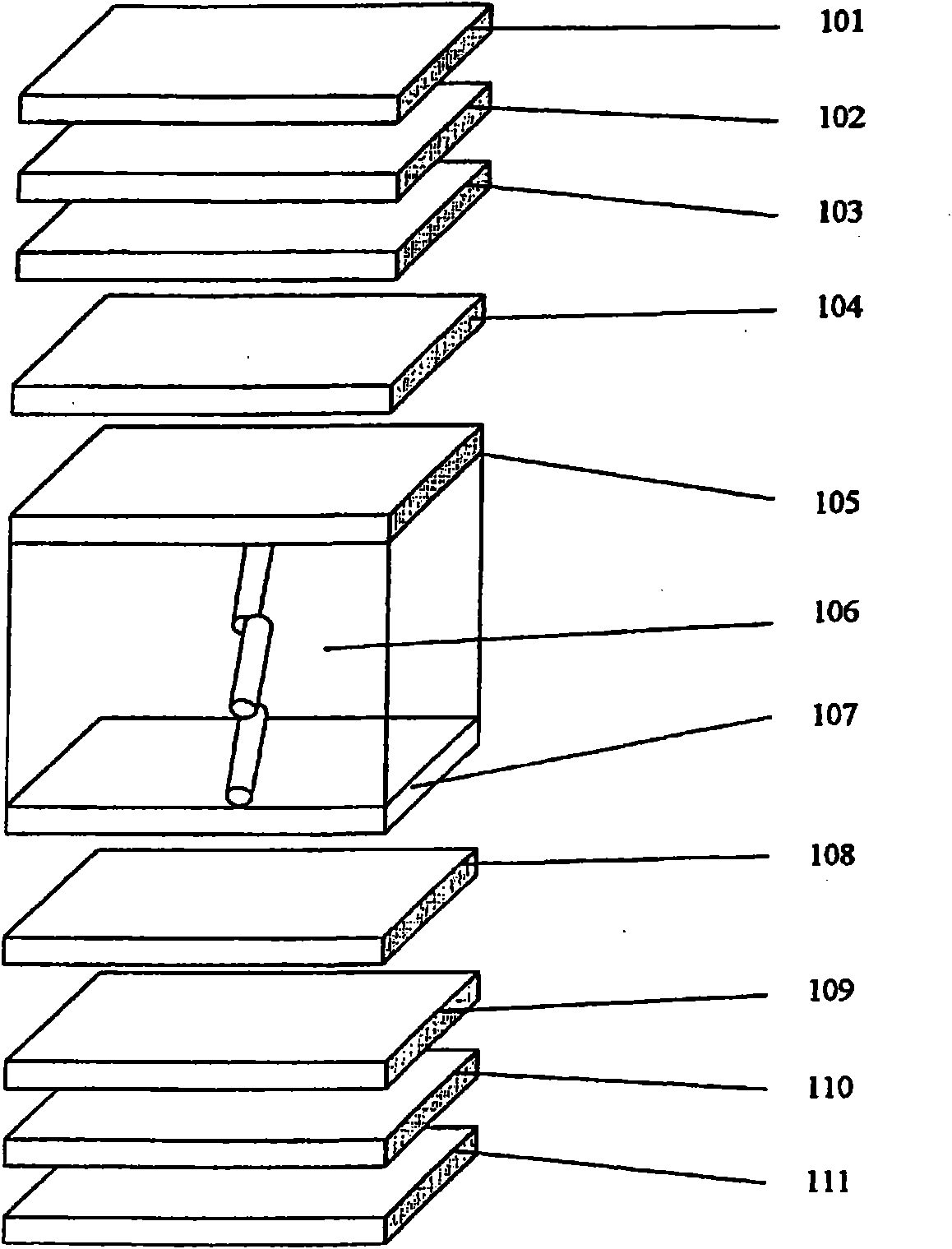
[0357] The VA (Vertical Alignment) liquid crystal display device according to Embodiment 2-1 of the present invention includes: a liquid crystal cell, two polarizers arranged outside the liquid crystal cell, and a liquid crystal cell arranged between the two polarizers The optically anisotropic layer in either of the two spaces of . The optically anisotropic layer contains a lactone ring-containing polymer, and the in-plane retardation Re and the thickness direction retardation Rth of the optically anisotropic layer satisfy the following formulas (A) and (B),
[0358] (A)40nm≤Re(550)≤275nm
[0359] (B)0nm≤Rth(550)≤275nm
[0360] Where Re(550) and Rth(550) represent in-plane retardation (nm) and thickness direction retardation (nm) at a wavelength of 550 (nm).
[0361] The VA (Vertical Alignment) liquid crystal display device according to Embodiment 2-2 of the present invention includes: a liquid crystal cell, two polarizers arranged outside the liquid crystal cell, and a liq...
Embodiment 1-1~1-8
[0586] The layer structure of a liquid crystal display device using a lactone film on the side closest to the light source when viewed from the liquid crystal cell is shown in Figure 5 . A TAC film is used in each optically anisotropic layer.
[0587] The front and back polarizers and optical compensatory sheets of the VA mode liquid crystal TV (LC30-AD1, manufactured by Sharp Corporation) panel were peeled off, and the polarizer made was bonded so that the transmission axis of the polarizer was in the vertical direction of the screen on the observation side, And the transmission axis of the polarizer is in the horizontal direction of the screen on the light source side.
PUM
| Property | Measurement | Unit |
|---|---|---|
| thickness | aaaaa | aaaaa |
| thickness | aaaaa | aaaaa |
| thickness | aaaaa | aaaaa |
Abstract
Description
Claims
Application Information
 - R&D Engineer
- R&D Manager
- IP Professional
- Industry Leading Data Capabilities
- Powerful AI technology
- Patent DNA Extraction
Browse by: Latest US Patents, China's latest patents, Technical Efficacy Thesaurus, Application Domain, Technology Topic, Popular Technical Reports.
© 2024 PatSnap. All rights reserved.Legal|Privacy policy|Modern Slavery Act Transparency Statement|Sitemap|About US| Contact US: help@patsnap.com


