
Liner for vacuum sockets, and use of the liner

A vacuum cylinder and lining technology, applied in medical science, prosthesis, etc., can solve problems such as not considering

Active Publication Date: 2010-10-06
OTTO BOCK HEALTHCARE IP GMBH & CO KG
View PDF0 Cites 4 Cited by
  • Summary
  • Abstract
  • Description
  • Claims
  • Application Information

AI Technical Summary

Problems solved by technology

Common vacuum liners on the market do not take into account the full residual limb surface for vacuum between liner and barrel

Method used


Image

  • Liner for vacuum sockets, and use of the liner
  • Liner for vacuum sockets, and use of the liner
  • Liner for vacuum sockets, and use of the liner

Examples


Embodiment Construction

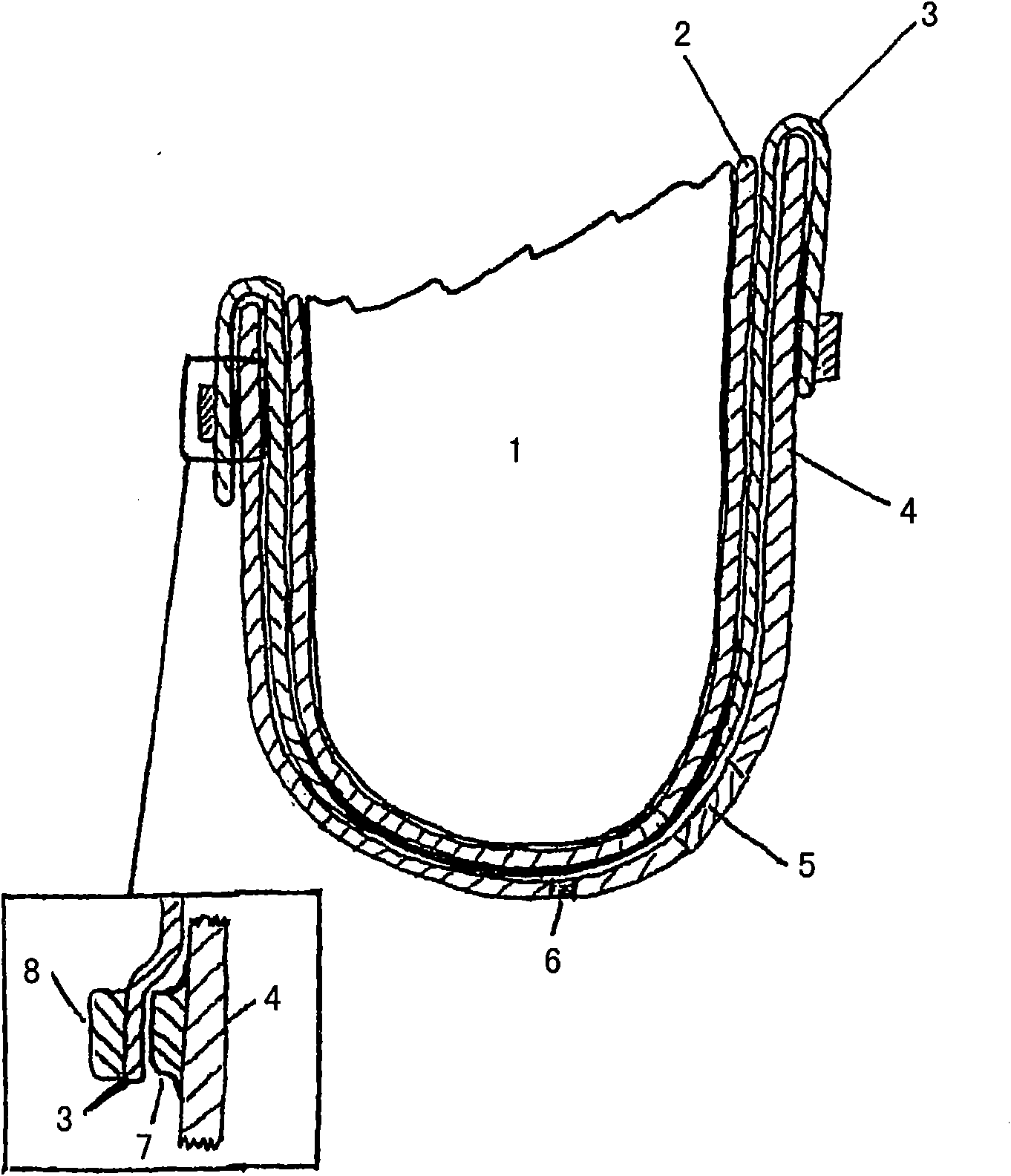
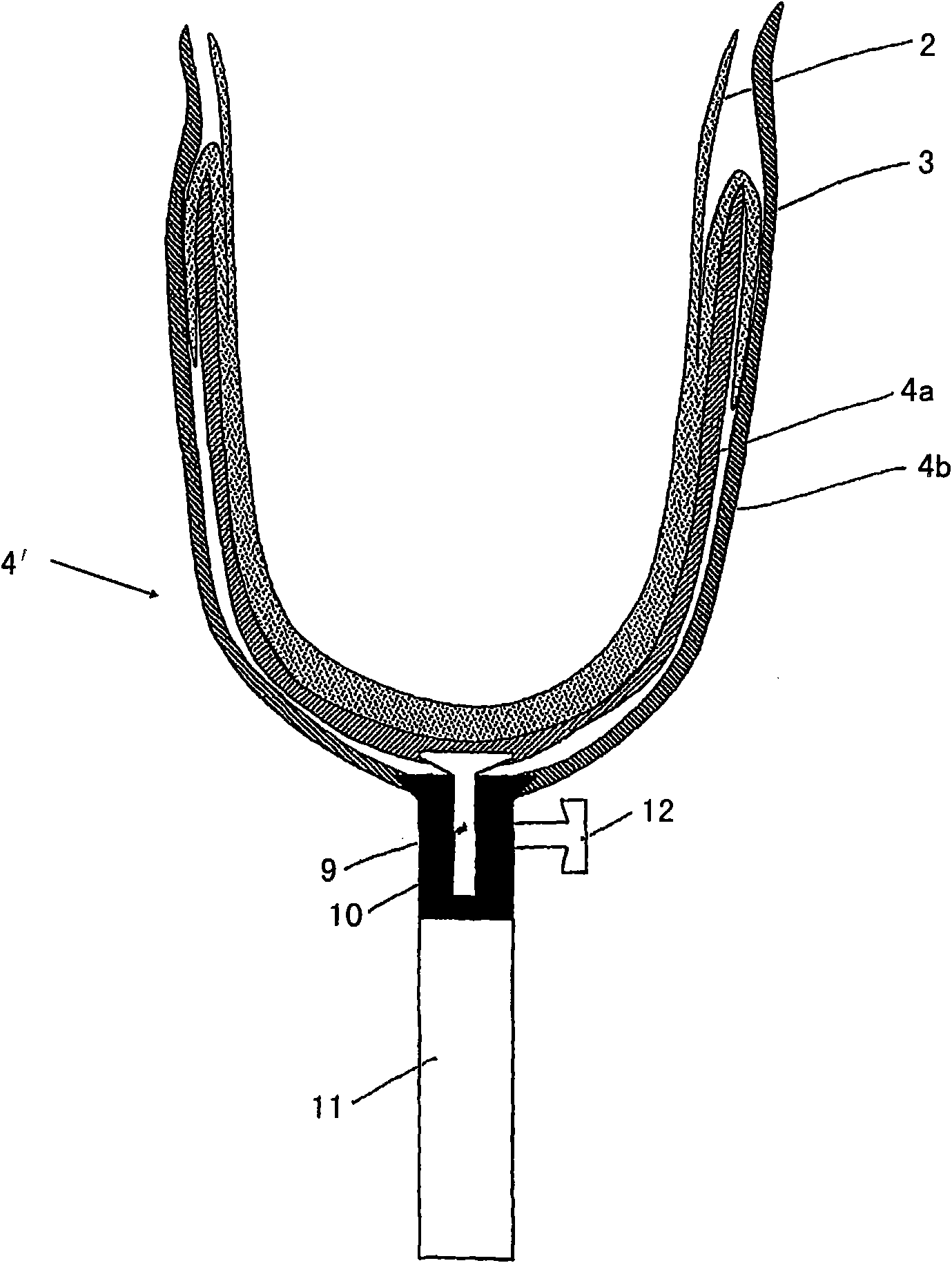
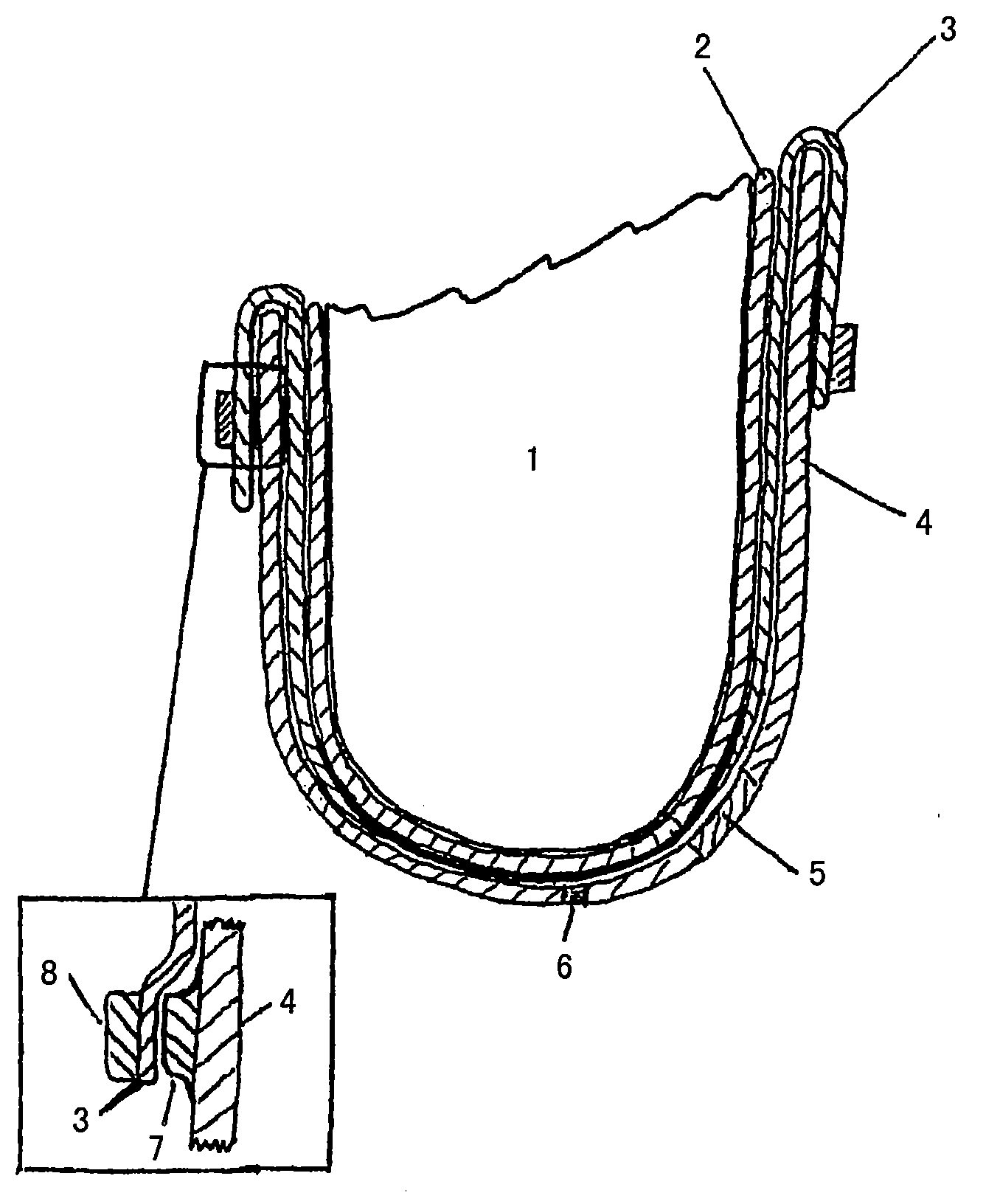
[0013] figure 1 The liner shown in comprises an inner liner 2 which is fixedly connected to the outer liner at the middle to the distal third, wherein the inner liner here also has a standard initial length. The liner can have a liner-specific distal shape by which longitudinal displacements are avoided, an individualized distal cup is used and which takes care of the necessary lateral expansion, etc.

[0014] To put the liner on, turn the complete liner inside out and roll the inner liner 2 over the stump. The individual mesial continuation of the edge of the inner lining can then be fixed and the inner lining shortened accordingly. The outer liner 3 is now folded proximally and the amputation stump 1 is inserted into the barrel 4 with the rolled up liner. The outer liner 3 is now folded distally onto the cartridge edge extension 4 and sealed on the outside of the cartridge 4 in order thereby to achieve a vacuum between the cartridge 4 and the linings 2 , 3 over the entire ...


PUM


Abstract

A liner for vacuum sockets for receiving amputation stumps and for use in prosthetic sockets, wherein the liner has a double wall made up of an inner liner (2) and of an outer liner (3), permits improved sealing by a vacuum between liner and prosthetic socket (4) by virtue of the fact that the inner liner (2) and the outer liner (3) are fixedly connected to each other in the middle third and / or distal third and that the outer liner (3) is designed to provide a seal with the prosthetic socket (4).

Description

technical field [0001] The invention relates to a liner for a vacuum cylinder for receiving an amputation stump, which liner is used in a prosthetic cylinder, wherein the liner is formed double-walled from an inner liner and an outer liner. [0002] Furthermore, the present invention also relates to the use of such liners and vacuum cylinders. Background technique [0003] In prosthetics, especially leg prostheses, efforts are made to achieve the largest possible surface area on the amputation stump for fastening the prosthesis. That is to say that the forces generated are distributed over as large a surface as possible not only during the load phase but also during the pivoting phase. So-called suction cylinders are suitable for achieving the largest possible surface area for fastening. The suction cartridge rests airtight on the amputation stump. If the force is suitable for withdrawing the prosthesis from the stump, a negative pressure is generated which, together with...

Claims


Application Information

Patent Timeline
Patent Type & Authority Applications(China)
IPC IPC(8): A61F2/78A61F2/80
CPCA61F2002/7837A61F2002/805A61F2/80A61F2002/7818
Inventor T-M·比勒费尔德
Owner OTTO BOCK HEALTHCARE IP GMBH & CO KG
Learn More