
Antenna element and array of antenna elements

A technology of antenna elements and antenna arrays, which is applied to antenna arrays, individually powered antenna arrays, antennas, etc., and can solve problems such as large arrays

Inactive Publication Date: 2010-09-29
ITI SCOTLAND
View PDF4 Cites 6 Cited by
  • Summary
  • Abstract
  • Description
  • Claims
  • Application Information

AI Technical Summary

Problems solved by technology

Although traveling wave elements are available that provide the wide bandwidth required for ultra-wideband networks, arrays of such elements are relatively large

Method used


Image

  • Antenna element and array of antenna elements
  • Antenna element and array of antenna elements
  • Antenna element and array of antenna elements

Examples


Embodiment Construction

[0041] Although the present invention is further described below for use in ultra-wideband networks, it should be understood that the present invention is applicable to other types of wireless communication networks.

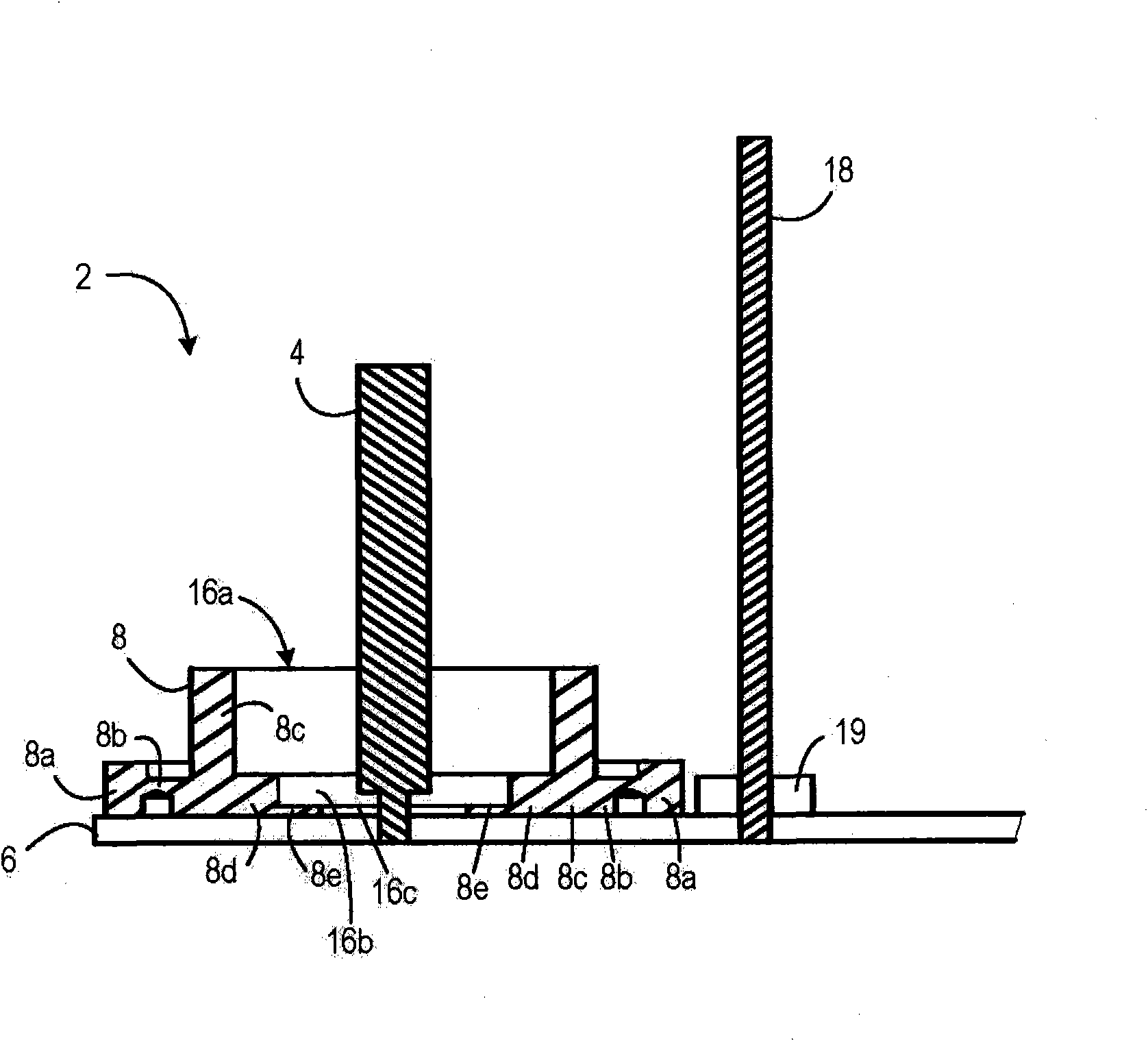
[0042] figure 2 A cross-sectional view of an antenna element 2 according to the invention is shown. The element 2 comprises a radiating element 4 in the form of an omnidirectional monopole arranged substantially perpendicular to the base plate 6 .

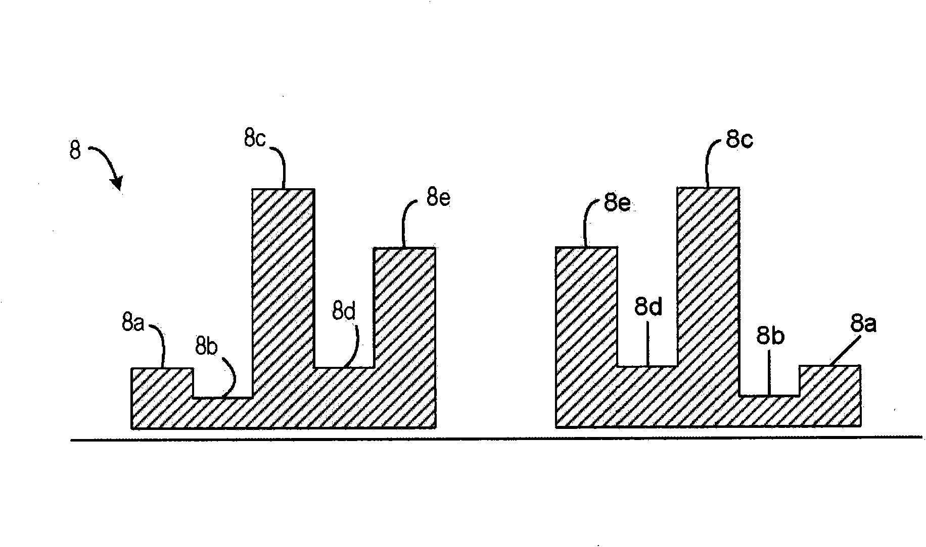
[0043] The antenna element 2 also comprises a frequency shaping device 8 arranged to "adapt" to the alternating current in the feed line of the radiating element 4 from the DC feed line. The frequency shaping device 8 is formed with a predetermined profile such that the frequency shaping device 8 affects the field radiated from the radiating element 4 in a large frequency range. Thus, the frequency shaping device 8 acts as a broad-banding device of the radiating element 4, which provides good return loss character...


PUM


Abstract

There is provided an antenna element for use in an ultra wideband network, the antenna element comprising a radiating element, for radiating signals over a range of frequencies in response to a signal received at a feed point; and a frequency shaping device located near the feed point of the radiating element for acting as a broad- banding device for the radiating element. A plurality of antenna elements may be formed into an antenna array.

Description

technical field [0001] The present invention relates to an antenna element, and more particularly, to an antenna element for use in an ultra-wideband network that maximizes signal strength and reduces interference. Background technique [0002] Ultra-wideband is a radio technology that transmits digital data over a very wide frequency range (3.1 to 10.6GHz). By spreading the RF energy over a large bandwidth, the transmitted signal is virtually undetectable by conventional frequency selective RF techniques. However, the low transmission power limits the communication distance to typically less than 10 to 15 meters. [0003] There are two approaches for UWB: a time-domain approach, which constructs a signal from a pulse waveform with UWB capabilities; and a frequency-domain modulation approach, which uses conventional FFT-based Orthogonal Frequency Division Multiplexing (OFDM) over multiple (frequency) bands , called MB-OFDM. The UWB method results in spectral components co...

Claims


Application Information

Patent Timeline
Patent Type & Authority Applications(China)
IPC IPC(8): H01Q9/30H01Q15/00H01Q19/32H01Q21/20
CPCH01Q21/205H01Q9/30H01Q15/0006H01Q19/32
Inventor 迪安·肯普迈克尔·菲利普帕基斯尼尔·威廉斯
Owner ITI SCOTLAND
Learn More