Measuring method of transconductance parameters
A measurement and parameter technology, used in measurement devices, measurement of electrical variables, electronic circuit testing, etc., can solve the problem of increasing the test cost of inverter oscillator circuit measurement time, and achieve the goal of reducing test cost and measurement time. Effect
- Summary
- Abstract
- Description
- Claims
- Application Information
AI Technical Summary
Problems solved by technology
Method used
Image
Examples
Embodiment
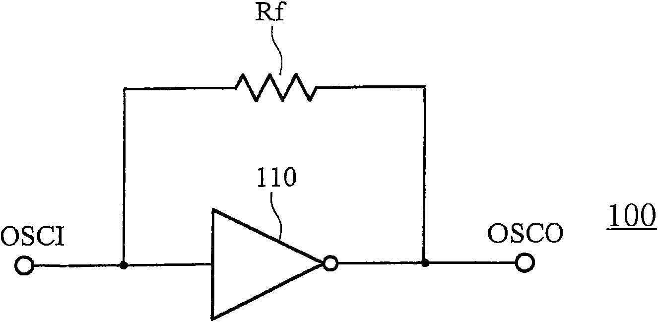
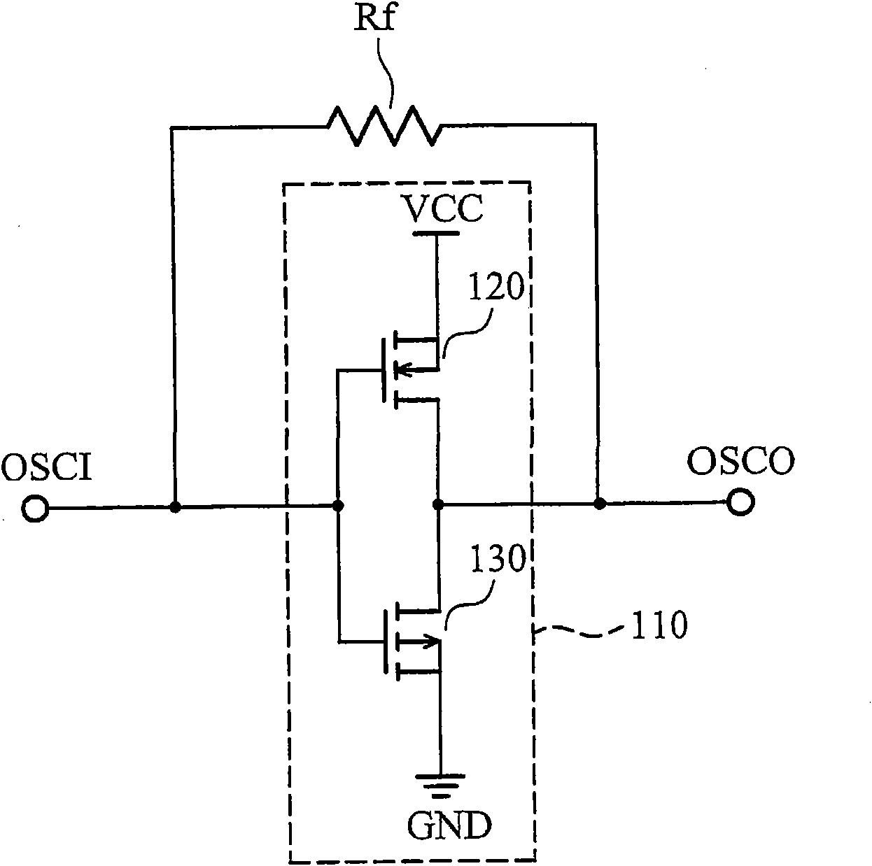
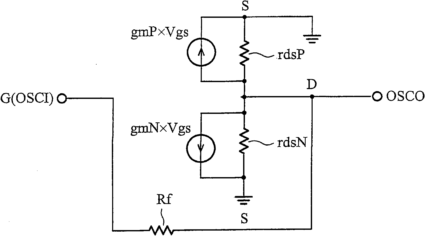
[0038] Figure 3 to Figure 6B A measuring circuit for measuring the transconductance of an inverter oscillator circuit according to an embodiment of the present invention is shown. image 3 A measuring circuit is shown for measuring the voltage value of the bias voltage in the oscillator circuit of the inverter. First, the input terminal OSCI and the output terminal OSCO are floating. Next, measure the voltage at the output terminal OSCO to obtain the bias voltage V bias . exist image 3 , due to the current I flowing through the feedback resistor Rf Rfis zero, so the voltages at the output terminal OSCO and the input terminal OSCI have the same bias voltage V bias voltage value.
[0039] Figure 4 A measurement circuit is shown for measuring the resistance value of the feedback resistor Rf in the inverter oscillation circuit. exist Figure 4 Among them, the DC voltage source 410 is coupled to the input terminal OSCI for providing the DC voltage to the inverter oscill...
PUM
 Abstract
Description
Claims
Application Information
 - R&D Engineer
- R&D Manager
- IP Professional
- Industry Leading Data Capabilities
- Powerful AI technology
- Patent DNA Extraction
Browse by: Latest US Patents, China's latest patents, Technical Efficacy Thesaurus, Application Domain, Technology Topic, Popular Technical Reports.
© 2024 PatSnap. All rights reserved.Legal|Privacy policy|Modern Slavery Act Transparency Statement|Sitemap|About US| Contact US: help@patsnap.com


