
LED lamp structure with mosquito catching function

A technology of structure and function of LED lamps, which can be applied to devices for catching or killing insects, damage prevention measures for lighting devices, and cooling/heating devices for lighting devices, etc.

Inactive Publication Date: 2010-09-22
陈文进 +2
View PDF0 Cites 4 Cited by
  • Summary
  • Abstract
  • Description
  • Claims
  • Application Information

AI Technical Summary

Problems solved by technology

[0002] The traditional method of killing mosquitoes is usually to spray chemical insecticides to eliminate insects and mosquitoes. However, chemical insecticides are sprayed towards the air and dissipated in the air. After being inhaled by the human body, it will cause harm and cause more damage to the environment. It has adverse effects, so it has gradually reduced its use and replaced it with non-polluting mosquito lamps.
[0003] Mosquito traps use the phototaxis of mosquitoes to attract mosquitoes. Generally, they are composed of LED light-emitting elements, fans and wire nets. The light-emitting elements emit light to attract mosquitoes to fly in, and then use the fan to inhale them. In addition, the bottom of the LED is heated and dried (heat convection rises) to starve to death; however, in general daily life, the occasions where mosquito lamps are needed are not all dimly lit environments, so that the trapping effect is not as good as expected, and the mosquito trap The high-voltage power grid on the lamp can easily cause children to be injured by mistake. Therefore, there are still many improvements to be made in the current mosquito trap lamp.

Method used


Image

  • LED lamp structure with mosquito catching function
  • LED lamp structure with mosquito catching function
  • LED lamp structure with mosquito catching function

Examples


Embodiment Construction

[0015] In the following, specific embodiments will be described in detail in conjunction with the accompanying drawings, so that it will be easier to understand the purpose, technical content, features and effects of the present invention.

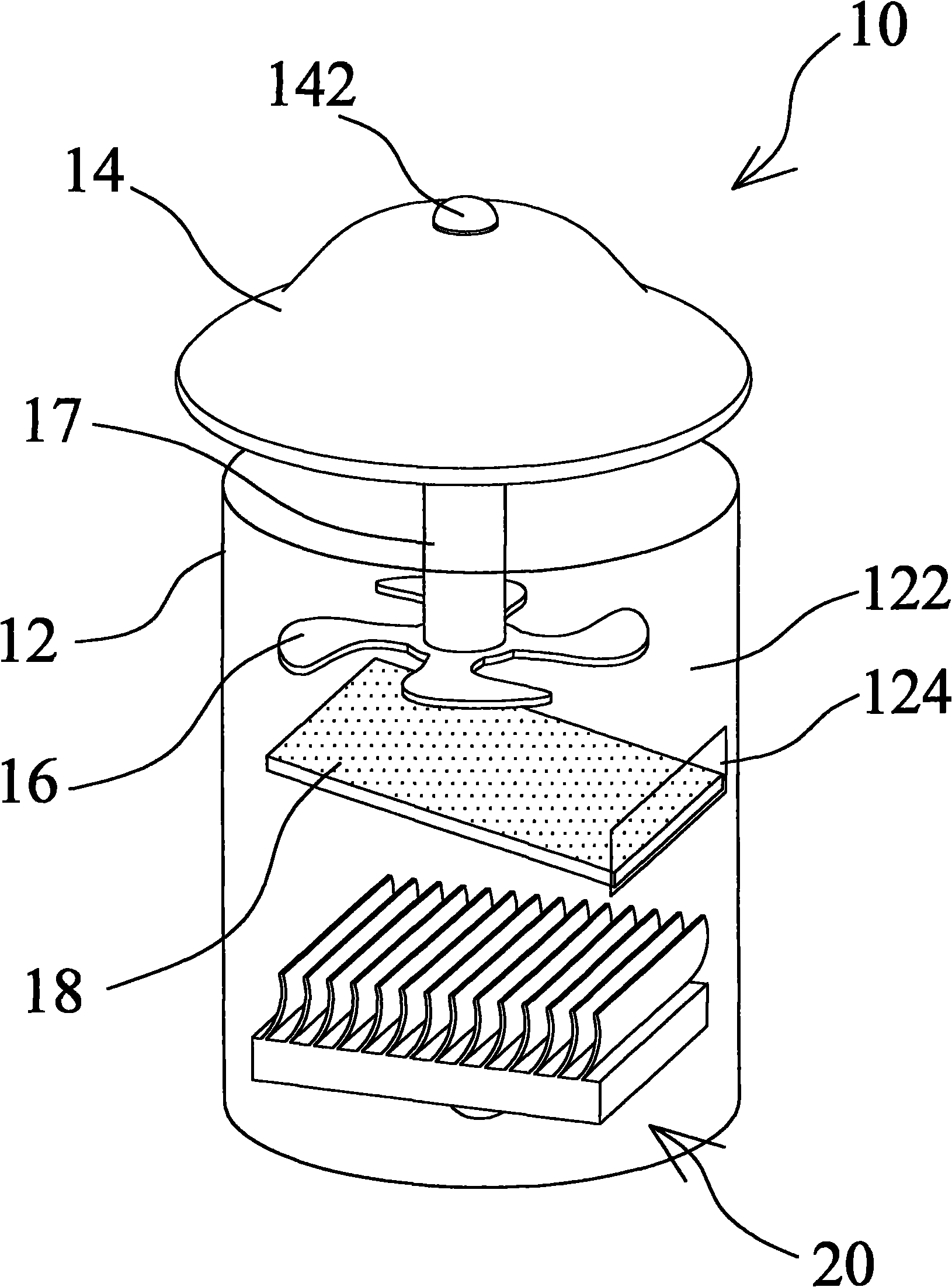
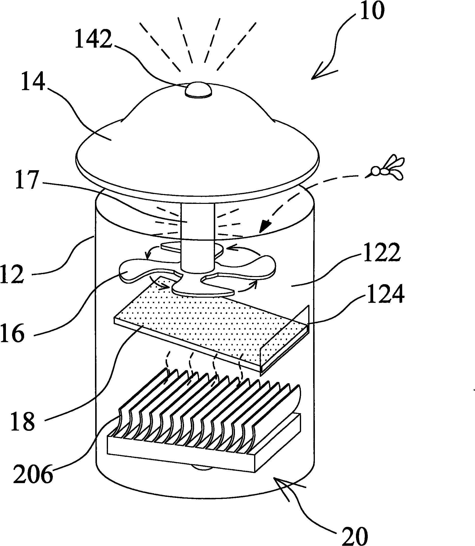
[0016] figure 1 It is a schematic diagram of the three-dimensional structure of the present invention. As shown in the figure, the present invention is an LED lamp structure 10 with a mosquito-catching function. The LED lamp structure 10 with a mosquito-catching function further includes a housing 12, and the housing 12 has a housing There is a space 122, one side of the housing 12 has an opening 124; a cover 14 is located above the housing 12, and a light emitting element 142 is provided on the cover 14, the light emitting element 142 can emit light, and the phototaxis of mosquitoes is used to attract mosquitoes There is a gap between the cover 14 and the housing 12; a fan 16 is located in the accommodating space 122, the fan 16 can gener...


PUM


Abstract

The invention discloses an LED lamp structure with mosquito catching function, comprising a housing, a cover, a fan, an oblique plate and an LED module, wherein the housing comprises an accommodating space; the cover is provided with a light emitting element and arranged above the housing and keeps a certain gap with the housing; the fan is arranged in the holding space and is used for leading the air to rotate and further sucking mosquitoes; the oblique plate is arranged in the housing and below the fan and is used for holding the mosquitoes sucked by the fan; the LED module is arranged above the oblique plate and is used for radiating heat; and the LED module comprises a superconducting element, at least one LED and a radiating fin, wherein the superconducting element can be used for transmitting the heat radiated by the LED to the oblique plate through the radiating fin, so that the mosquitoes fallen on the oblique plate are killed at high temperature and are sucked by being matched with the sucking air flow of the fan. The LED lamp structure uses the air flow generated by the fan to suck the mosquitoes, thereby having good catching effect; and the low power consumption property of the LED is further matched, thereby achieving the power-saving and environment-friendly mosquito catching effect and being applicable to mass production.

Description

technical field [0001] The present invention relates to a mosquito trapping lamp, in particular to an LED lamp structure with a mosquito trapping function which is combined with an LED lamp light-emitting diode module and utilizes a heat dissipation heat source to extinguish mosquitoes. Background technique [0002] The traditional method of killing mosquitoes is usually to spray chemical insecticides to eliminate insects and mosquitoes. However, chemical insecticides are sprayed towards the air and dissipated in the air. After being inhaled by the human body, it will cause harm and cause more damage to the environment. It has adverse effects, so it has been gradually reduced in use and replaced by non-polluting mosquito lamps. [0003] Mosquito traps use the phototaxis of mosquitoes to attract mosquitoes. Generally, they are composed of LED light-emitting elements, fans and wire nets. The light-emitting elements emit light to attract mosquitoes to fly in, and then use the f...

Claims


Application Information

Patent Timeline
Patent Type & Authority Applications(China)
IPC IPC(8): F21S2/00F21V15/02F21V29/02A01M1/06F21Y101/02F21V29/51F21V29/67F21V29/76
Inventor 陈文进陈志朗陈坤川
Owner 陈文进
Learn More