Marking and/or leveling device

A technology for leveling and marking, which is used in measuring devices, active optical measuring devices, measuring instruments, etc., and can solve the problems of high structure, cumbersome and high cost of pendulum system.

Inactive Publication Date: 2010-09-15
ROBERT BOSCH GMBH
View PDF1 Cites 3 Cited by
  • Summary
  • Abstract
  • Description
  • Claims
  • Application Information

AI Technical Summary

Problems solved by technology

The disadvantage of this robust pendulum system is the cumbersome and costly production of the cross joint, which must work with very little friction
[0003] Furthermore, all known pendulum systems have the disadvantage that they are relatively tall and generally require a separate pendulum damper, so that lengthy leveling operations are avoided

Method used


Image

  • Marking and/or leveling device
  • Marking and/or leveling device
  • Marking and/or leveling device

Examples


Embodiment Construction

[0018] In the figures, identical structural elements and structural elements having the same function are identified with the same reference numerals.

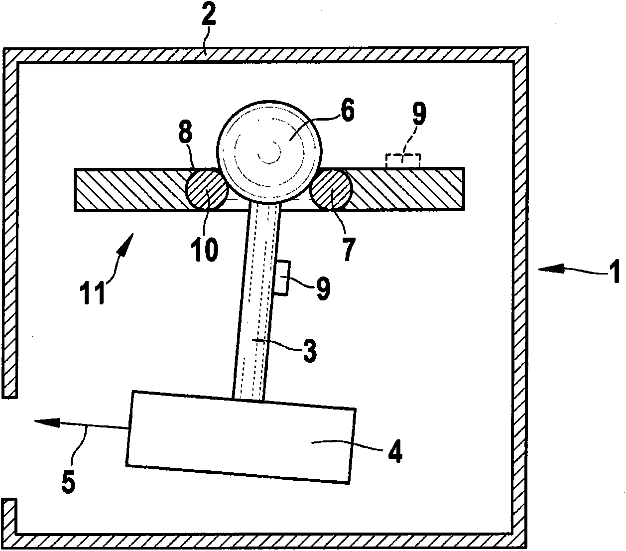
[0019] exist figure 1 The marking and / or leveling device 1 is shown schematically in FIG. The marking and / or leveling device comprises a housing 2 and a pendulum 3 , which is mounted pivotably relative to the housing 2 in all spatial directions relative to the housing 2 . The pendulum 3 is designed as a rigid linkage element and carries, on its lower end in the plane of the drawing, a light source 4 designed as a laser diode for generating a point-shaped or linear laser beam 5 along the cross-section. , with which a point-shaped or linear horizontal laser line can be projected onto the projection plane.

[0020] At the upper end facing the light source 4 in the plane of the drawing, the rigid pendulum 3 has a ball head 6 which, together with the annular bearing receptacle 7 , forms a self-aligning bearing 8 . The bearing re...


PUM


Abstract

The invention relates to a marking and / or leveling device (1) comprising a light source (4) disposed on a pendulum (3) that can pivot relative to a housing (2). According to the invention, means are provided for accelerating (9) the pendulum (3) and / or a pendulum bearing (8) in a pulsing manner.

Description

technical field [0001] The invention relates to a marking and / or leveling device according to the preamble of claim 1 . Background technique [0002] Marking and / or leveling devices with pendulum systems of different configurations for vertically or horizontally orienting light sources are disclosed. In a first disclosed embodiment, the pendulum carrying the light source is configured as a wire or rope. The disadvantage of this pendulum system is that it is particularly sensitive to vibrations and is difficult to stabilize or level. In a second disclosed embodiment of the pendulum system, the pendulum system comprises a rigid pendulum which bears on the edge or point of the knife. A disadvantage is the sensitivity of the pendulum system to collisions. In a third disclosed embodiment, the pendulum system comprises a rigid pendulum which is supported in the form of a cross joint (keel joint). A disadvantage of such a robust pendulum system is the complex and cost-intensive...

Claims


Application Information

Patent Timeline
IPC IPC(8): G01C15/00G02B27/64
CPCG01C15/004
Inventor R·富克斯
Owner ROBERT BOSCH GMBH
Why Eureka
Try Eureka