
WNN planetary reduction gear with large transmission ratio

A technology of planetary deceleration and large transmission ratio, which is applied in transmission devices, gear transmission devices, belts/chains/gears, etc. It can solve the problems of difficult processing of eccentric shafts, low reduction ratios, complex structures, etc., and achieve processing difficulty The effect of small size, large carrying capacity and high transmission efficiency

Inactive Publication Date: 2010-09-15
哈尔滨东建机械制造有限公司
View PDF5 Cites 2 Cited by
  • Summary
  • Abstract
  • Description
  • Claims
  • Application Information

AI Technical Summary

Problems solved by technology

The disadvantages and deficiencies of this planetary reduction device mainly include: 1. The structure is more complicated 2. The eccentric shaft is difficult to process 3. The reduction ratio is relatively not very high

Method used


Image

  • WNN planetary reduction gear with large transmission ratio
  • WNN planetary reduction gear with large transmission ratio
  • WNN planetary reduction gear with large transmission ratio

Examples


Embodiment 1

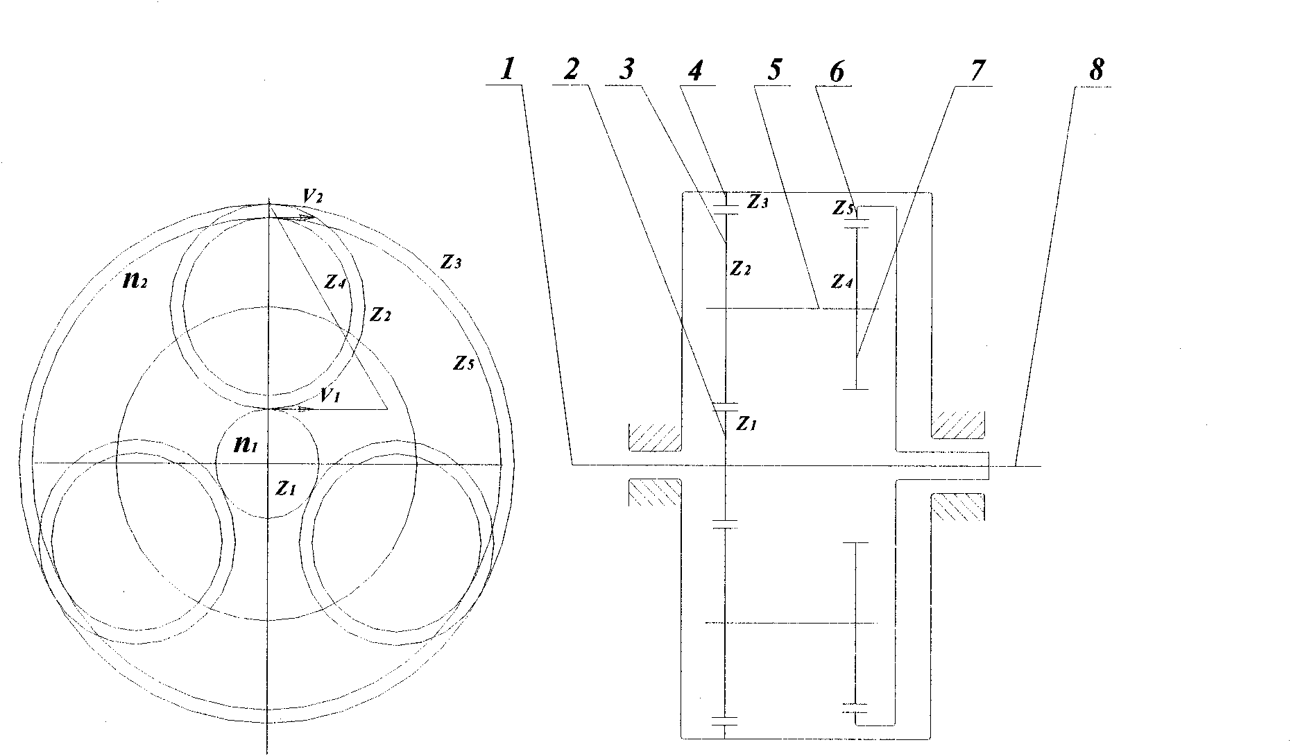
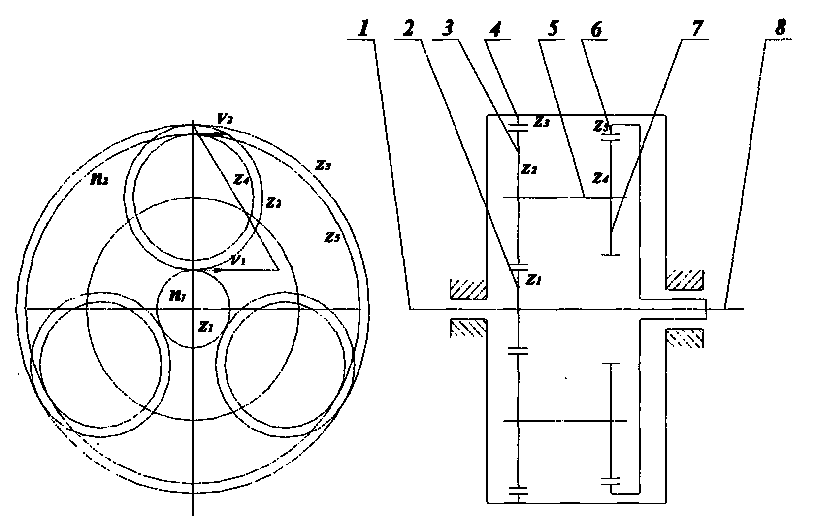
[0018] Example 1: Combining figure 2 , the present invention is a WNN planetary reduction device with large transmission ratio, which is composed of input shaft (1), gear Z1 (2), gear Z2 (3), gear Z3 (4), intermediate shaft (5), gear Z4 ( 7), gear Z5 (6) and output shaft (8), the input shaft (1) is connected to gear Z1 (2), gear Z1 (2) is connected to gear Z2 (3), and gear Z2 (3) is connected to the intermediate shaft ( 5), the intermediate shaft (5) is connected to the gear Z4 (7), the gear Z4 (7) is connected to the gear Z5 (6), and the gear Z5 (6) is connected to the output shaft (8).

Embodiment 2

[0019] Example 2: Combining figure 2 , a WNN planetary reduction device with a large transmission ratio of the present invention does not use an eccentric frame to drive the internal gear pair, but designs a pair of external transmission gear pairs Z1, Z2, and the central shaft of the gear Z2 (3) drives two internal gear pairs.

[0020] The transmission principle of the present invention: the motor drives the input shaft to rotate, the gear Z1 rotates accordingly, and the gear Z2 meshing with it rotates. Since the gear Z3 is fixed, the three gears Z2 are forced to revolve along the gear Z3 in addition to rotating around the central axis. , and the gear Z2 rotates, drives the coaxial gear Z4 to rotate, and drives the internal gear Z5 meshed with it to rotate, and the gear Z5 is integrated with the output shaft, and then drives the output shaft to rotate.

Embodiment 3

[0021] Example 3: Binding figure 2 , the present invention is a WNN planetary reduction device with a large transmission ratio, and the transmission ratio is calculated as follows: from figure 2 Velocity triangle relationship in , we get:

[0022] V2=V1×(Z2-Z4) / Z2

[0023] n1=V1 / Z1×π

[0024] n2=V2 / Z5×π

[0025] And Z5=Z1+Z2+Z4

[0026] Therefore, the transmission ratio i=n1 / n2=Z2×(Z1+Z2+Z4) / Z1×(Z2-Z4)


PUM


Abstract

The invention provides a WNN planetary reduction gear with a large transmission ratio, comprising an input shaft, a gear Z1, a gear Z2, a gear Z3, a middle shaft, a gear Z4, a gear Z5 and an output shaft, wherein the input shaft is connected with the gear Z1, the gear Z1 is connected with the gear Z2, the gear Z2 is connected with the middle shaft, the middle shaft is connected with the gear Z4, the gear Z4 is connected with the gear Z5, and the gear Z5 is connected with the output shaft. The WNN planetary reduction gear has large transmission ratio and adopts different tooth differences, and meanwhile, the difference values of the Z4, the Z2, the Z5 and the Z3 are small. Meanwhile, compared with an ordinary planetary reduction gear, the WNN planetary reduction gear is additionally provided with first-stage speed reduction (an external transmission gear pair of Z1 and Z2), and a result of i=30-200 can be obtained; the input and the output turns to the same direction; and the WNN planetary reduction gear has the property of self-locking during reverse transmission. The WNN planetary reduction gear has large carrying capacity, compact structure, small volume, high transmission efficiency and small processing difficulty.

Description

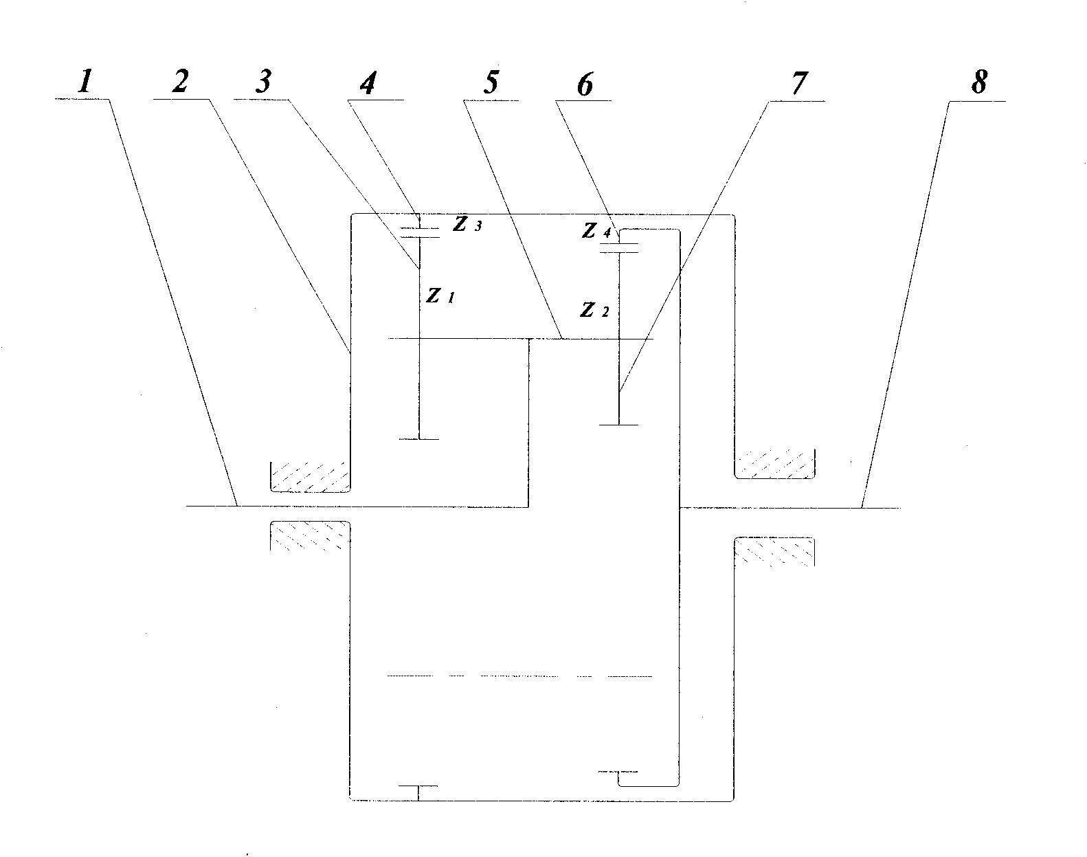
(1) Technical field [0001] The invention relates to mechanical transmission technology, specifically a WNN planetary reduction device with a large transmission ratio. (2) Background technology [0002] At present, the NN-type planetary reduction gear with a large transmission ratio generally uses an eccentric frame (or eccentric shaft) to drive the internal gear pair and small tooth difference technology. From figure 1 Look at it, the motor drives the eccentric frame to rotate, and drives the two pairs of internal gear pairs Z1, Z2, Z3, Z4 on the eccentric frame to rotate, the gear Z3 is fixed, and the gear Z1 revolves along the gear Z3 in addition to rotating around the eccentric shaft, and drives the gear Z2 rotates, and drives the internal gear Z4 meshed with it to rotate, and the gear Z4 is integrated with the output shaft, which drives the output shaft to rotate. The disadvantages and deficiencies of this planetary reduction device mainly include: 1. The structure is ...

Claims


Application Information

Patent Timeline
IPC IPC(8): F16H1/32
Inventor 樊滨
Owner 哈尔滨东建机械制造有限公司
Learn More