Positioning and clamping device and method for milling small-size flat long and thin parts

A milling processing and clamping device technology, which is applied in positioning devices, metal processing equipment, metal processing machinery parts, etc., can solve the problems that affect the total time of the processing process, reduce production efficiency, and increase labor intensity of workers, etc.

Inactive Publication Date: 2011-08-31
DONGHUA UNIV
View PDF0 Cites 0 Cited by
  • Summary
  • Abstract
  • Description
  • Claims
  • Application Information

AI Technical Summary

Problems solved by technology

For a certain mass production, the degree of automation of clamping will seriously affect the total time of the processing process
Manual clamping will increase the labor intensity of workers and reduce production efficiency

Method used


Image

  • Positioning and clamping device and method for milling small-size flat long and thin parts
  • Positioning and clamping device and method for milling small-size flat long and thin parts
  • Positioning and clamping device and method for milling small-size flat long and thin parts

Examples


Embodiment 1

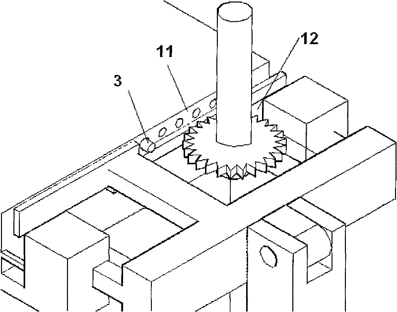
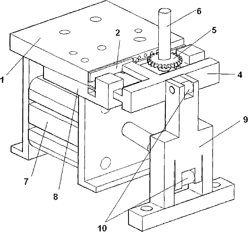
[0022] Such as figure 2 , image 3 As shown, a positioning and clamping device for milling of small flat and slender parts includes a clamp body 1, a clamping element 4, a guide element 8, a cylinder 7 and a transmission hinge 10, and the side of the clamp body 1 has a concave There are at least two positioning holes beside the groove, and the positioning holes are provided with a limit pin 3. The guide element 8 is connected to the bottom of the clamp body 1, and a guide groove is provided in the middle, and the clamping element 4 is connected to On the fixed frame 9, the fixed frame 9 is connected with the cylinder 7, and is located directly in front of the groove of the clip body 1.

[0023] The clamping element 4 has clamping arms facing the direction of the clamping body 1, and the clamping arms on the left and right sides are located in the guide grooves of the guide element 8, and the cylinder 7 is located below the guide element 8 and passes through the front telesco...


PUM


Abstract

The invention relates to a positioning and clamping device for milling small-size flat long and thin parts. The positioning and clamping device is characterized in that: a groove is formed on the lateral surface of a clamp body (1); at least two positioning holes are formed on the side of the groove; a limit pin (3) is arranged on each positioning holes; a guiding element (8) is connected below the clamp body (1), and a guiding groove is formed on the middle part of the guiding element; a clamping element (4) is connected to a holder (9); the holder (9) is connected with a cylinder (7) and ispositioned in front of the groove of the clamp body (1); the clamping element (4) is provided with clamping arms in a direction which is opposite to the clamp body (1); the clamping arms of left and right sides are positioned in the guiding groove of the guiding element (8); the cylinder (7) is positioned below the guiding element (8) and is connected with the holder (9) through an expansion linkin front of the guiding element; and the positioning and clamping device is arranged on an operating platform of a numerically controlled milling machine. The positioning and clamping device can improve the integral machining accuracy, machining quality and the production efficiency of machining the parts.

Description

technical field [0001] The invention belongs to the technical field of mechanical processing, in particular to a positioning and clamping device and method for processing small flat and slender parts. Background technique [0002] The extensive use of machining centers has greatly changed the production mode of the machinery manufacturing industry. Small machining centers have a greater advantage in price and are more widely used. Most of these machining centers are vertical structures. If small flat and slender parts are to be processed (such as figure 1 ) on the planar structure, the position of the part during processing must be perpendicular to the workbench. [0003] Usually, the processing of such parts can use multiple copy mills and special feeding and clamping mechanisms. Its disadvantage is that multiple clamping is required, it is difficult to adjust after changing the tool, and it is difficult to ensure the consistency of the processing size. The machining ce...

Claims


Application Information

Patent Timeline
Patent Type & Authority Patents(China)
IPC IPC(8): B23Q3/06
Inventor 朱世根张永宇丁浩罗治平
Owner DONGHUA UNIV
Why Eureka
Try Eureka