Hole sowing roller device

A drum and hole sowing technology, which is applied to the parts of the seeder and the machine for interval quantitative sowing, can solve the problems of cumbersomeness, inconvenient adjustment of the seed box, and complicated structure of the seed box, and achieve the goal of reducing the void rate and strengthening the strength. Effect

Inactive Publication Date: 2011-11-16
陈恒
View PDF2 Cites 0 Cited by
  • Summary
  • Abstract
  • Description
  • Claims
  • Application Information

AI Technical Summary

Problems solved by technology

The device mainly includes: a hole sowing drum, a negative pressure suction pipe, and an air-suction seed divider. The main shafts of the seeders are driven by gears, and the gears installed on the main shafts of the air-suction seed divider are internal gears; the advantage of this device is that the seeds are not easy to fall out during the rotation of the hole sowing drum, and the sowing speed can be increased. The structure of the present invention It is simple and compact, with precise hole sowing and precise hole spacing. It is suitable for high-speed sowing devices. The disadvantage of this device is that it is necessary to set up a seed transfer box when the seeds fall from the air-suction seed divider to the duck's mouth. Such a structure , it is relatively cumbersome to adjust the plant spacing when sowing different crops
But the disadvantage is that the structure of the seed box is relatively complicated, especially when sowing seeds with different plant spacings, it is still inconvenient to adjust the seed box

Method used


Image

  • Hole sowing roller device
  • Hole sowing roller device
  • Hole sowing roller device

Examples


Embodiment Construction

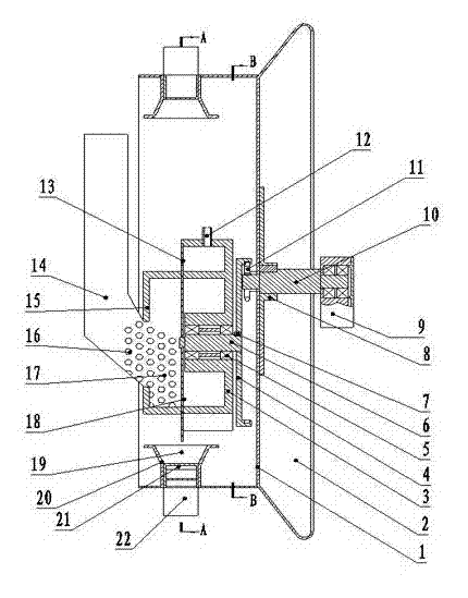
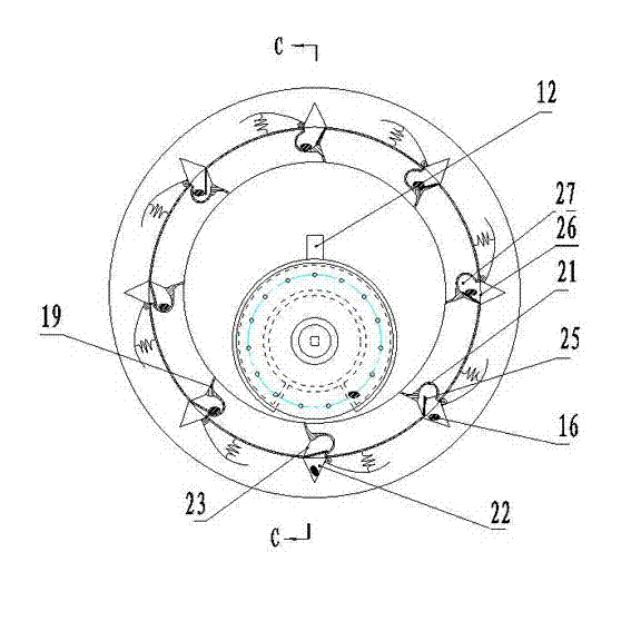
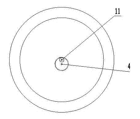
[0014] Such as Figure 1-6 Schematic, the labels in the figure: 1-hole sowing roller, 2-press film wheel, 3-air suction seed divider, 4-driven internal gear, 5-seeder bearing, 6-air suction seed divider main shaft , 7-key, 8-reinforcing disc, 9-traction frame, 10-pit sowing roller main shaft, 11-driving gear, 12-suction pipe, 13-suction hole, 14-seed box, 15-filling seat, 16 -seeds, 17-filling chamber, 18-suction plate, 19-baffle, 20-groove seed delivery channel, 21-seed bin, 22-duck beak, 23-seed hole, 24-hinge shaft, 25 - dodge door, 26 - seed outlet, 27 - storage room.

[0015] The present invention mainly includes a hole sowing drum 1, a duck mouth 22, a film pressing wheel 2, an air suction type seed divider 3, an air suction pipe 12, and a seed box 14. The main shaft 10 is connected with the main shaft 6 of the air-suction type seed divider through gears. It is characterized in that a trough-shaped seed delivery channel 20 is arranged on the inner side of the outer rin...


PUM


Abstract

The invention relates to a farm seeder, in particular to a roller device used on a pneumatic film laying hill seeder. The roller device mainly comprises a hole sowing roller, duck nozzles, a film laminating wheel, a pneumatic seed dividing device, an air suction pipe and a seed box, wherein the pneumatic seed dividing device is arranged in the hole sowing roller; the main shaft of the hole sowingroller is connected with the main shaft of the pneumatic seed dividing device through a gear; a groove-shaped seed conveying passage is arranged in the peripheral direction on the inner side of the outer ring of the roller; a seed chamber 21 is arranged at the seed inlet of each duck nozzle 22; a movable door 25 is also arranged at the seed inlet through a hinged shaft 25; a driven internal gear on the main shaft of the pneumatic seed dividing device is in suspension matching with a gear of the main shaft of the hole sowing roller; and the seed box is fixedly connected with the pneumatic seeddividing device. Seeds enter the seed chamber from the seed inlet along the arc groove-shaped seed conveying passage so that the seeds are conveyed into a hole sowing nozzle after the roller rotates at 360 degree; the phenomenon that the seeds easily flip out in the process in which the seeds enter duck nozzles is avoided; and therefore, empty hole rate of hole sowing is reduced. In addition, theseed chamber is simple in structure and easily assembled so that different crops with different planting distance requirements are conveniently planted. The farm seeder has another advantage that thegroove-shaped seed conveying passage strengthens the strength of the roller.

Description

technical field [0001] The invention relates to an agricultural seeder, in particular to a hole sowing roller device used on an air-suction precision film-laying hole seeder. Background technique [0002] Chinese patent literature discloses a kind of air-suction precision seeding device on February, 2010, and publication number is CN201393383, and this patent technology is developed by the inventor. The device mainly includes: a hole sowing drum, a negative pressure suction pipe, and an air-suction seed divider. The main shafts of the seeders are driven by gears, and the gears installed on the main shafts of the air-suction seed divider are internal gears; the advantage of this device is that the seeds are not easy to fall out during the rotation of the hole sowing drum, and the sowing speed can be increased. The structure of the present invention It is simple and compact, with precise hole sowing and precise hole spacing. It is suitable for high-speed sowing devices. T...

Claims


Application Information

Patent Timeline
Patent Type & Authority Patents(China)
IPC IPC(8): A01C7/18A01C7/20
Inventor 陈恒
Owner 陈恒
Why Eureka
Try Eureka