
Section storage rack

A technology for storage racks and profiles, which is applied to storage devices, transportation and packaging, etc., can solve the problems of large storage area, low hoisting operation efficiency, hidden dangers, etc., and achieves simple production and installation, improved operating efficiency, and convenient hoisting operations. Effect

Inactive Publication Date: 2010-09-08
龙工(福建)液压有限公司
View PDF6 Cites 4 Cited by
  • Summary
  • Abstract
  • Description
  • Claims
  • Application Information

AI Technical Summary

Problems solved by technology

[0002] At present, heavy material warehousing enterprises, metal material production enterprises, logistics enterprises, mechanical processing enterprises, etc. have no stereotyped storage equipment for the storage of profiles, but basically use seamless stacking, and the material layers are generally stacked with wooden strips, profiled steel or Isolation of thick straw ropes, etc., this kind of stacking has the following disadvantages: 1. It is difficult to realize the management concept of first-in-first-out of materials; 2. When storing a small amount of multi-variety materials, it takes up a large storage area. If many different materials are stacked together , Difficult to retrieve materials; 3. It is impossible to store in isolation, the marking is not obvious, and materials of different materials are easy to confuse; 4. It is difficult to achieve multi-point horizontal support for materials during long-term storage, and the material deformation is serious; Low operating efficiency; 6. When the material is stacked too high, there is a great potential safety hazard; 7. The stacking on site is messy, and civilized production cannot be realized

Method used

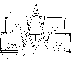
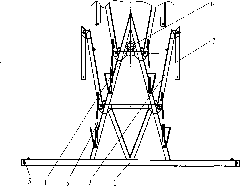
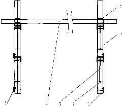

Image

  • Section storage rack
  • Section storage rack
  • Section storage rack

Examples


Embodiment Construction

[0016] The present invention will be described in further detail below in conjunction with the accompanying drawings and specific embodiments.

[0017] Such as Figure 1 ~ Figure 3 As shown, the profile storage rack of the present invention connects two or more storage racks in series through the connecting pipe 4 to form a storage rack group; each storage rack includes an "A"-shaped main support frame 1, a space layer support beam 2 and its legs 7 , reset gas spring 3, connecting buckle 5 and connecting sleeve 6 located on the upper part of the "A"-shaped main support frame, arranged in three layers; the space layer support beam 2 connects with the "A"-shaped main support frame 1 through one end of the pin shaft Hinged, the other end is hinged with one end of the support foot 7, the other end of the support foot 7 can be fixed or loosened with the support beam of the next layer through the connecting buckle 5, and the angle between the support beam 2 of the space layer and th...


PUM


Abstract

The invention discloses a section storage rack. More than two single storage racks are connected in series through a connecting pipe (4) to form a storage rack set; each single storage rack consists of an A-shaped main support frame (1), a space layer supporting beam (2), a supporting foot (7) of the space layer supporting beam (2), a return air spring (3), a connecting buckle (5) and a connecting sleeve (6) positioned on the upper part of the A-shaped main support frame, and the components are arranged in a plurality of layers; one end of the space layer supporting beam (2) is movably connected with the A-shaped main support frame (1), and the other end of the space layer supporting beam (2) is movably connected with one end of the supporting foot (7); the other end of the supporting foot (7) can be fixed to or separated from the supporting beam at the lower layer of the supporting foot (7) through the connecting buckle (5); and the return air spring is arranged between each space layer supporting beam and the A-shaped main support frame. The section storage rack with the structure achieves the purposes of making the stored material get in the rack first and making the stored material get out of the rack first and ensuring small occupation of land, tidy stacking, convenient management of stacking and taking of the different materials and safe and high-efficiency hoisting operation.

Description

1. Technical field [0001] The invention relates to a storage device, in particular to a profile storage device. 2. Background technology [0002] At present, heavy material warehousing enterprises, metal material production enterprises, logistics enterprises, mechanical processing enterprises, etc. have no stereotyped storage equipment for the storage of profiles, but basically use seamless stacking, and the material layers are generally stacked with wooden strips, profiled steel or Isolation of thick straw ropes, etc., this kind of stacking has the following disadvantages: 1. It is difficult to realize the management concept of first-in-first-out of materials; 2. When storing a small amount of multi-variety materials, it takes up a large storage area. If many different materials are stacked together , Difficult to retrieve materials; 3. It is impossible to store in isolation, the marking is not obvious, and materials of different materials are easy to confuse; 4. It is diff...

Claims


Application Information

Patent Timeline
Patent Type & Authority Applications(China)
IPC IPC(8): B65G1/04
Inventor 陈桂清
Owner 龙工(福建)液压有限公司
Learn More