Full-depth three-dimensional control dragger
A three-dimensional control and towing body technology, which is applied to special-purpose ships, ships, motor vehicles, etc., can solve the problems of large pitch angle of the towing body, single purpose, unsuitable for carrying acoustic or optical sensors, etc., to avoid excessive pitch angle , to ensure the effect of smooth operation
- Summary
- Abstract
- Description
- Claims
- Application Information
AI Technical Summary
Problems solved by technology
Method used
Image

Examples
Embodiment 1
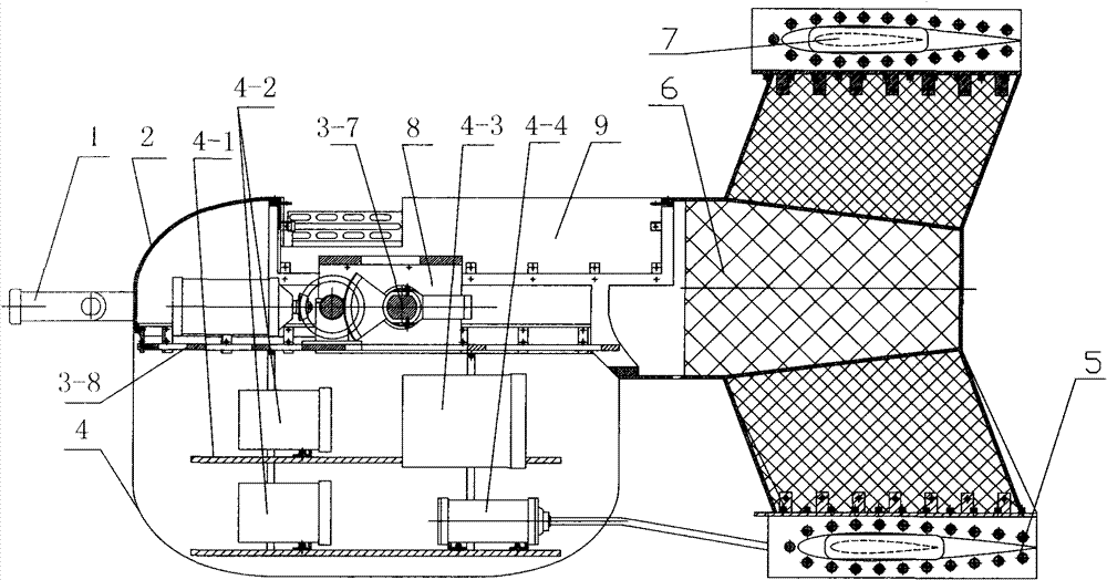
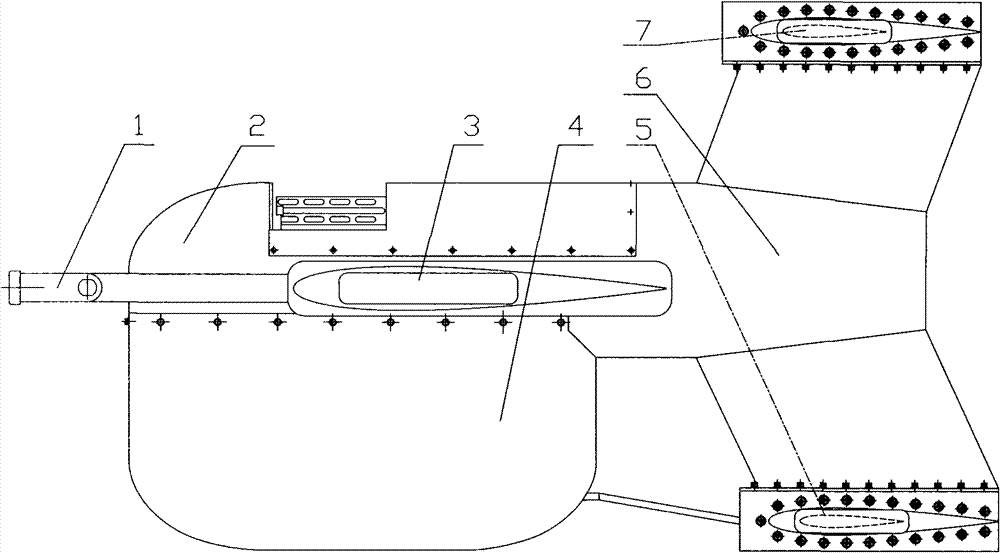
[0022] Embodiment 1: refer to Figure 1-8 . Large-depth three-dimensional control drag body, including streamlined main body 2, swept wing 3, empennage, enclosure 4 and tow bar 1, swept wing 3 is connected on both sides of streamlined main body 2, empennage is connected at the tail of streamlined main body 2, surrounded The basket 4 is connected below the streamlined main body 2, and the rotating shaft 3-7 of the swept wing 3 is connected with the towing bar 1. The empennage is "I" shaped, and it is controlled by the empennage mount 6, the automatic roll control device 7 and the empennage. Machinery 5 is formed, and the middle part of empennage fixed mount 6 is fixedly connected with streamlined main body 2 afterbody, and the upper end of empennage fixed mount 6 is connected with automatic roll control device 7, and its lower end is connected with empennage control machinery 5.
[0023] The streamlined main body 2 is provided with a sensor cabin 9 and a swept wing control cab...
Embodiment 2
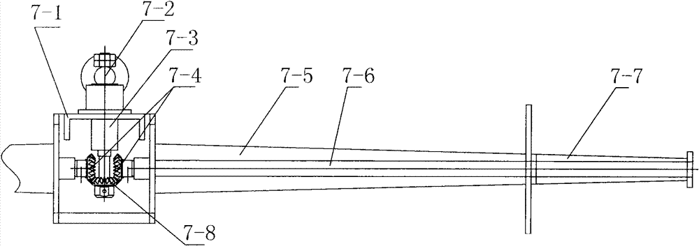
[0024] Embodiment 2: refer to figure 1 , 2 and 3. Described automatic roll control device 7 comprises installation box 7-1, fixed wing 7-5, adjusting wing 7-7, rotating shaft 1 7-6, helical gear 7-4, helical gear 1 7-8, fork 7- 3 and weight 7-2, the lower end of the installation box 7-1 is fixedly connected with the upper end of the empennage fixed frame 6, the fixed wings 7-5 are respectively fixedly connected to both sides of the installation box 7-1, and the rotating shaft 1 7-6 passes through the installation box 7-1 and the fixed wing 7-7 are fixedly connected with the adjusting wing 7-5, and the rotating shaft 1 7-6 is located in the installation box 7-1, and one end is respectively connected with a helical gear 7-4, and one end of the fork 7-3 is located in the installation box 7-1, the other end is located outside the installation box 7-1, the middle part is hinged with the inner wall upper end of the installation box 7-1, and the end of the swing rod 7-3 located in ...
Embodiment 3
[0025] Embodiment 3: refer to figure 1 , 2 , 4 and 5. Described empennage control mechanism 5 comprises installation box I 5-1, fixed wing I 5-5, adjusting wing I 5-6, rotating shaft II 5-3, worm gear 5-4 and worm screw 5-2, installation box I 5-1 The upper end is fixedly connected to the lower end of the empennage fixing frame 6, the fixed wing I 5-5 is respectively fixedly connected to both sides of the installation box I 5-1, and the rotating shaft II 5-3 traverses the installation box I 5-1 and the fixed wing I 5-5 , its two ends are respectively fixedly connected with the adjusting wing I 5-6 on the outside of the fixed wing I 5-5, the worm gear 5-4 is fixedly connected with the middle part of the rotating shaft II 5-3 and is located in the installation box I 5-1, the worm 5- 2. One end is connected with the installation box I 5-1, and the other end goes out of the installation box I 5-1, and the action section of the worm screw 5-2 meshes with the worm wheel 5-4.
PUM
 Abstract
Description
Claims
Application Information
 - Generate Ideas
- Intellectual Property
- Life Sciences
- Materials
- Tech Scout
- Unparalleled Data Quality
- Higher Quality Content
- 60% Fewer Hallucinations
Browse by: Latest US Patents, China's latest patents, Technical Efficacy Thesaurus, Application Domain, Technology Topic, Popular Technical Reports.
© 2025 PatSnap. All rights reserved.Legal|Privacy policy|Modern Slavery Act Transparency Statement|Sitemap|About US| Contact US: help@patsnap.com