
Device for sleeving bearing ring

A technology of bearing rings and bearing outer rings, applied in bearing components, shafts and bearings, mechanical equipment, etc., can solve the problems of easy failure, small application scope, complex mechanism, etc., to achieve simplified mechanism, convenient model change, no need The effect of debugging

Inactive Publication Date: 2010-09-01
NINGBO HUILIAN AUTOMATIC EQUIP +3
View PDF4 Cites 11 Cited by
  • Summary
  • Abstract
  • Description
  • Claims
  • Application Information

AI Technical Summary

Problems solved by technology

[0012] In order to overcome the disadvantages of complex mechanism, small application range, easy failure and high cost in the prior art, the present invention provides a bearing sleeve with simple structure, wide application range, simple and fast model replacement, less prone to machine failure, and low cost ring assembly

Method used


Image

  • Device for sleeving bearing ring
  • Device for sleeving bearing ring
  • Device for sleeving bearing ring

Examples


Embodiment Construction

[0037] With reference to accompanying drawing, further illustrate the present invention:

[0038] The assembly device of the bearing ring includes a frame 1, and the frame 1 is provided with:

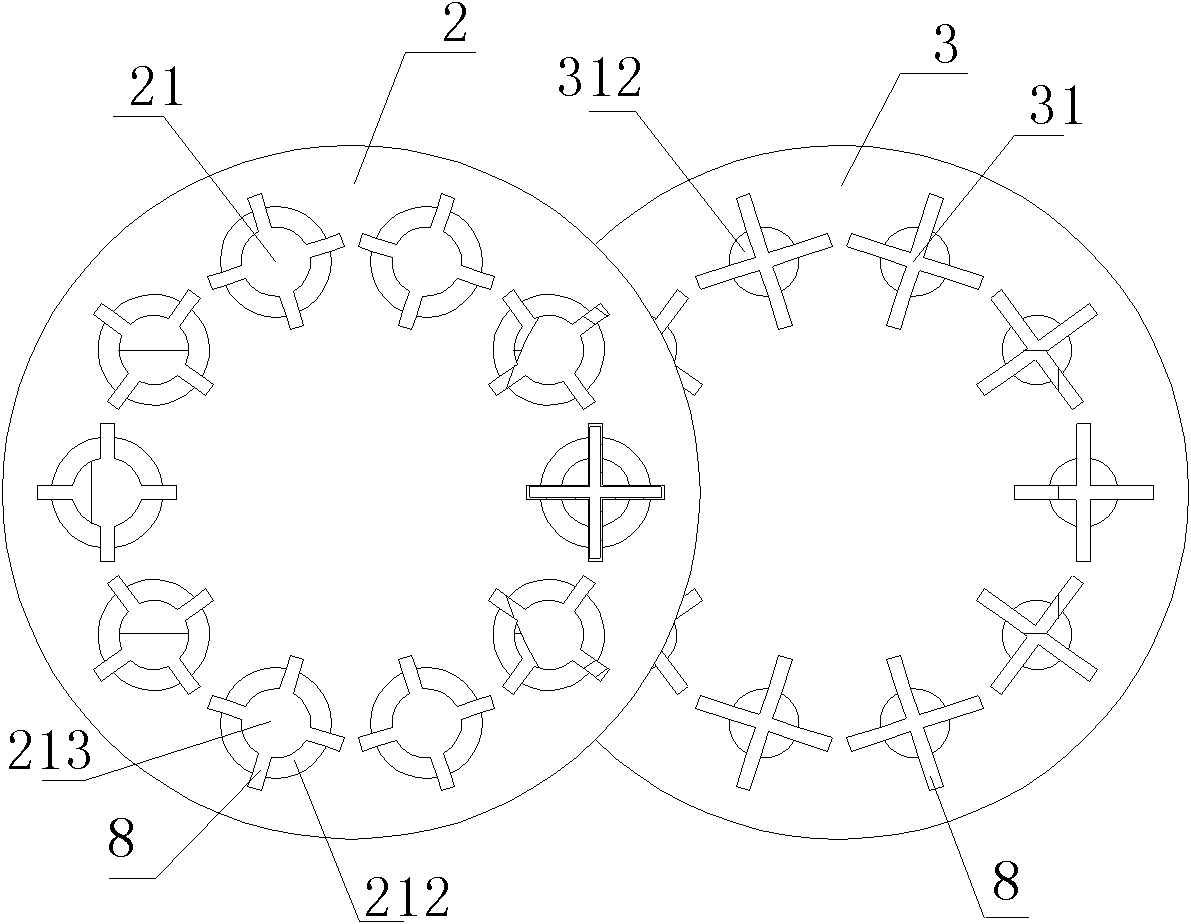
[0039] The outer ring storage tray 2 carrying the outer ring of the bearing and the inner ring storage tray 3 carrying the inner ring of the bearing are the measuring mechanisms for measuring the size of the ferrule respectively, and the measured ferrules are respectively sent to the transfer material of the corresponding storage tray Mechanism, a combination mechanism for combining the inner and outer rings, and a discharge mechanism for discharging the combined rings; the storage trays 2 and 3 are respectively linked with the respective controllable motors 6 and 7, and the two Each of the controllable motors is controlled by a controller that can record the position of the incoming ferrule, and can automatically select the inner and outer rings to prepare for matching. The controller ...


PUM


Abstract

The invention provides a device for sleeving a bearing ring. The device comprises a frame, a feeding mechanism, a ring sleeving mechanism and a discharging mechanism, wherein an outer ring storage plate and an inner ring storage plate are arranged on the frame; the outer ring storage plate and the inner ring storage plate are connected with each controllable motor respectively; the outer ring storage plate and the inner ring storage plate are horizontally arranged; the inner ring storage plate is arranged under the outer ring storage plate; storage holes are formed on the outer ring storage plate and the inner ring storage plate, are uniformly distributed along peripheries, and comprise accommodation chambers and brackets; an outer ring storage hole is necessarily formed on the outer ring storage plate and is overlapped with an inner ring storage hole which is formed on the inner ring storage plate up and down to form a ring sleeving channel; a through hole which allows an inner ring to pass through is formed on the bottom of the outer ring storage hole; a ring sleeving cylinder is positioned under the ring sleeving channel; a push rod of the ring sleeving cylinder is fixedly connected with a push block which can push a ring in the ring sleeving channel upwards till the ring leaves the outer ring storage plate, wherein the length of the push block is greater than the diameter of the storage holes; and a through groove which can allows the push block to pass through is formed on a side wall of the storage holes. The device for sleeving the bearing rings has the advantages of simple structure, quick model replacement, wide application range, rare occurrence of machine fault, and low cost.

Description

technical field [0001] The invention relates to a fitting device of a bearing ring. technical background [0002] The fitting mechanism of the bearing ring is one of the indispensable parts in the bearing production equipment, and its purpose is to fit the inner and outer rings of the bearing. [0003] Bearings are mechanical parts that require high precision. Therefore, when fitting the sets, the grooves of the inner and outer rings of the bearing must be measured first. According to the required bearing clearance requirements, inner and outer rings with different dimensional accuracy must be selected. Match it with the matching steel ball. [0004] The existing bearing ring fitting mechanism includes an outer ring measuring head for measuring the channel size of the outer ring, an inner ring measuring head for measuring the channel size of the inner ring, an outer ring storage tray for storing the outer ring of the bearing, and a storage tray for storing the inner ring of...

Claims


Application Information

Patent Timeline
Patent Type & Authority Applications(China)
IPC IPC(8): F16C43/04
Inventor 张惠邦张慧才
Owner NINGBO HUILIAN AUTOMATIC EQUIP
Learn More