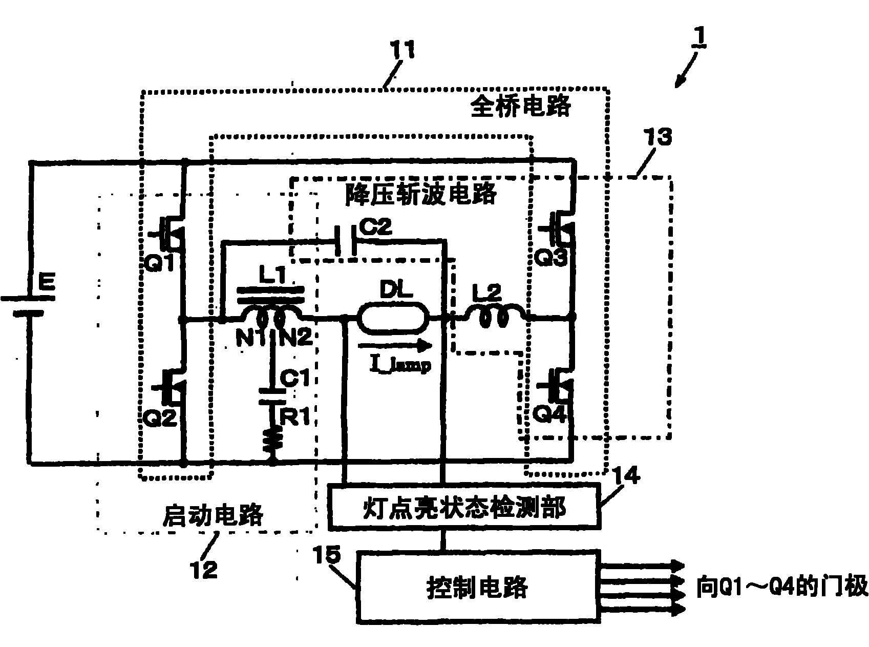
High pressure discharge lamp ballast, lighting device and lighting system
A high-pressure discharge lamp and lighting device technology, which is applied in the field of lighting systems, can solve problems such as rising costs and complexity, and achieve the effect of sufficient heating
Inactive Publication Date: 2010-08-25
PANASONIC CORP
View PDF3 Cites 5 Cited by
- Summary
- Abstract
- Description
- Claims
- Application Information
AI Technical Summary
Problems solved by technology
However, in order to realize the above-mentioned method, a detection circuit and a control circuit with a complicated structure are required, and cost increases accompanied by an increase in the number of parts occur.
Method used
View moreImage
Smart ImageViewing Examples
Examples
Embodiment approach 1
Embodiment approach 2
Embodiment approach 3
Login to View More PUM
 Abstract
The invention relates to a high pressure discharge lamp ballast, a lighting device and a lighting system, which can meet an electrode require, adequately heat and form a stable discharge without making the circuit structure complex. The high pressure discharge lamp ballast (1) comprises a full-bridge circuit (11) which converts DC power into AC power, a startup circuit (12) which generates a startup high voltage for breaking down the lamp (DL) insulation, a buck chopper (13) which reduces the output voltage of a DC power supply (E) and outputting to the full-bridge circuit (11), a lamp ballast state detection unit (14) which detects the lamp (DL) ballast state, and a control circuit (15) which controls the full-bridge circuit (11) and the startup circuit (13). The control circuit (15) sets the lamp power supply during the electrode heating period when the lamp is started according to an accumulation ballast time detected by the lamp ballast detection unit (14).
Description
technical field The present invention relates to a high-pressure discharge lamp lighting device for lighting a high-pressure discharge lamp, a lighting fixture using the same, and a lighting system constructed of a plurality of lighting fixtures. Background technique Conventionally, high-intensity high-pressure discharge lamps called HID (High-Intensity Discharge) have been widely used mainly for vehicles. In this high-pressure discharge lamp, since discharge needs to be generated in the lamp during lighting, a lighting device including a power conversion circuit that inputs DC power and outputs AC power, and a control circuit that controls the power conversion circuit is required. As a high-pressure discharge lamp lighting device, it has been proposed to set the ignition period (hereinafter referred to simply as "phase 1") in which a control circuit raises the voltage of a power conversion circuit and applies a voltage to a high-pressure discharge lamp to cause dielectric ...
Claims
Login to View More Application Information
Patent Timeline
 Patent Type & Authority Applications(China)
IPC IPC(8): H05B41/24
CPCH05B41/382H05B41/2887Y02B20/204Y02B20/00
Inventor 山原大辅小松直树
Owner PANASONIC CORP
Features
- R&D
- Intellectual Property
- Life Sciences
- Materials
- Tech Scout
- Unparalleled Data Quality
- Higher Quality Content
- 60% Fewer Hallucinations
Learn More Browse by: Latest US Patents, China's latest patents, Technical Efficacy Thesaurus, Application Domain, Technology Topic, Popular Technical Reports.
© 2025 PatSnap. All rights reserved.Legal|Privacy policy|Modern Slavery Act Transparency Statement|Sitemap|About US| Contact US: help@patsnap.com


