Photomultiplier tube

一种光电倍增管、电子倍增的技术,应用在电子倍增管、放电管、电子倍增器倍增极等方向,能够解决耐受电压降低等问题

Active Publication Date: 2010-08-25
HAMAMATSU PHOTONICS KK
View PDF4 Cites 6 Cited by
  • Summary
  • Abstract
  • Description
  • Claims
  • Application Information

AI Technical Summary

Problems solved by technology

Therefore, there is a case where the box is electrified and the withstand voltage (withstand voltage) decreases

Method used


Image

  • Photomultiplier tube
  • Photomultiplier tube
  • Photomultiplier tube

Examples


Embodiment Construction

[0020] Hereinafter, preferred embodiments of the photomultiplier tube according to the present invention will be described in detail with reference to the drawings. However, in the description of the drawings, the same reference numerals are assigned to the same or corresponding parts, and overlapping descriptions are omitted.

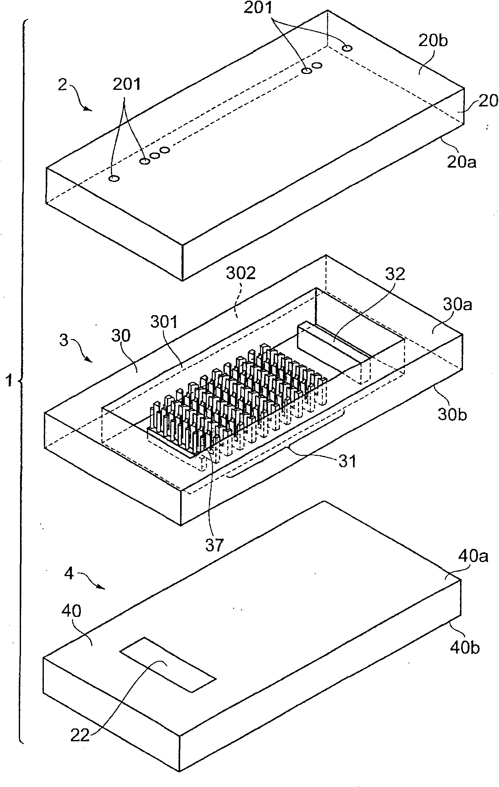
[0021] FIG. 1 is a perspective view of a photomultiplier tube 1 according to a preferred embodiment of the present invention, and FIG. 2 is an exploded perspective view of the photomultiplier tube 1 of FIG. 1 .

[0022] The photomultiplier tube 1 shown in FIG. 1 is a photomultiplier tube with a transmissive photoelectric surface, and has an upper frame 2 (second substrate), a side wall frame 3 (side wall portion), and an upper frame 2. The lower side frame 4 (first substrate) that faces the side wall frame 3 constitutes a box. This photomultiplier tube 1 is an electron tube, wherein, the direction in which light is incident on the photoelectric surfac...


PUM


Abstract

Electrons are prevented from being made incident onto an insulation part of a casing between dynodes to improve a withstand voltage. The photomultiplier tube (1) is a photomultiplier tube which is provided with substrates (20, 40) arranged so as to oppose each other, with the respective opposing surfaces (20a, 40a) made with an insulating material, a substrate (30) constituting a casing together with the substrates (20, 40), dynodes 31a to 31j arrayed on an opposing surface (40a) on the substrate (40) so as to be spaced away sequentially from a first end side to a second end side, a photocathode (22) installed so as to be spaced away from the dynode (31a) to the first end side, and an anode part (32) installed so as to be spaced away from the dynode (31j) to the second end side, in which the opposing surface (20a) of the substrate (20) is formed so as to cover the dynodes (31a to 31j), and a plurality of conductive layers (21a to 21j) set equal in potential to dynodes (31a to 31j) which are electrically independent from each other are installed at sites opposing individually the dynodes (31a to 31j) on the opposing surface (20a).

Description

technical field [0001] The present invention relates to a photomultiplier tube for detecting incident light from the outside. Background technique [0002] The development of small photomultiplier tubes using microfabrication technology has been progressing. For example, a planar photomultiplier tube is known in which a photodiode, a dynode, and an anode are arranged on a light-transmitting insulating substrate (see Patent Document 1 below). With such a configuration, weak light can be detected with high reliability, and the size of the device can also be realized. [0003] However, in the conventional photomultiplier tubes as described above, the dynodes of each stage are arranged on the insulating substrate of a box composed of an insulating substrate and a cap member. The multiplied electrons whose orbits are enlarged between the electron planes tend to be incident on the insulating substrate of the housing. This tendency is particularly noticeable in the case of minia...

Claims


Application Information

Patent Timeline
Patent Type & Authority Applications(China)
IPC IPC(8): H01J43/04H01J43/10
CPCH01J43/243H01J43/22
Inventor 下井英树木下仁志小玉刚史久嶋浩之
Owner HAMAMATSU PHOTONICS KK
Why Eureka
Try Eureka