Hardening equipment and method for manufacturing liquid crystal display panel
A technology of equipment and panels, applied in the field of liquid crystal display devices, can solve problems such as increased equipment costs, and achieve the effects of improving quality and speeding up production
- Summary
- Abstract
- Description
- Claims
- Application Information
AI Technical Summary
Problems solved by technology
Method used
Image
Examples
no. 1 example
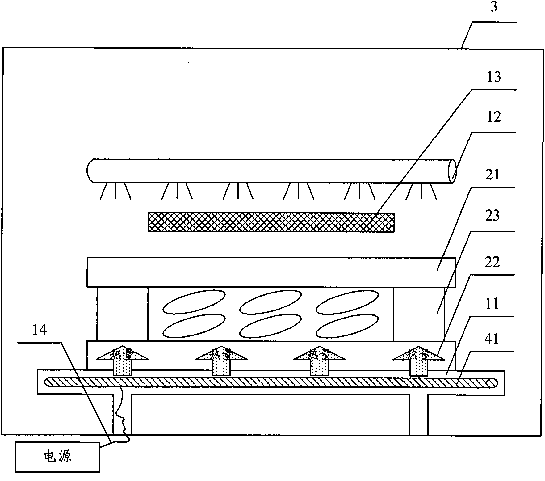
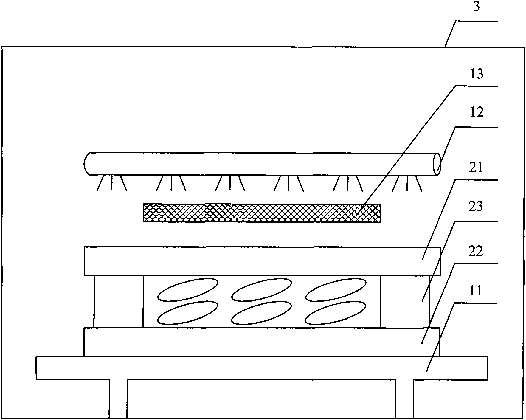
[0040] Fig. 3 is a schematic diagram of a first embodiment of the hardening apparatus of the present invention. As shown in Figure 3, hardening equipment of the present invention comprises:
[0041] The workbench 11 is used to place the panel and is located at the bottom of the reaction chamber 3. The workbench 11 is provided with a first area and a second area surrounded by the first area, and the first area and the panel are The non-display area corresponds to the adhesive in the panel, the second area corresponds to the display area of the panel, and the workbench 11 is provided with a heating device;
[0042] The ultraviolet lamp 12 is used to vertically irradiate the entire workbench 11 and is located on the top of the reaction chamber 3;
[0043] The light blocking plate 13 is used to cover the second area of the workbench 11 , that is, to cover the display area of the panel, and is located below the ultraviolet lamp 12 .
[0044] In the hardening setting of this...
no. 2 example
[0047] Fig. 4 is a schematic diagram of a second embodiment of the hardening device of the present invention. As shown in Figure 4, hardening equipment of the present invention comprises:
[0048]The workbench 11 is used to place the panel and is located at the bottom of the reaction chamber 3. The workbench 11 is provided with a first area and a second area surrounded by the first area, and the first area and the panel are Corresponding to the non-display area, that is, corresponding to the adhesive in the panel, the second area corresponds to the display area of the panel, and a ventilation duct 42 is opened in the workbench 11, and the ventilation duct 42 is provided with Air blowing holes 43 are used to blow hot air into the ventilation duct. The ventilation duct 42 is provided with air suction holes 44 for extracting hot air from the ventilation duct. The ventilation duct 42 passes through the air blowing holes 43 Connect with the air suction hole 44 and the hot gas ci...
no. 3 example
[0053] Fig. 5 is a schematic diagram of a third embodiment of the hardening device of the present invention. As shown in Figure 5, hardening equipment of the present invention comprises:
[0054] The workbench 11 is used to place the panel and is located at the bottom of the reaction chamber 3. The workbench 11 is provided with a first area and a second area surrounded by the first area, and the first area and the panel are The non-display area corresponds, that is, corresponds to the adhesive in the panel, the second area corresponds to the display area of the panel, and the workbench 11 is a transparent workbench, such as a glass substrate, a quartz substrate, etc., and An infrared lamp 45 is arranged under the workbench, that is, an infrared lamp 45 is arranged under the glass substrate to irradiate the panel evenly;
[0055] The ultraviolet lamp 12 is used to vertically irradiate the entire workbench 11 and is located on the top of the reaction chamber 3;
[0056] The ...
PUM
 Abstract
Description
Claims
Application Information
 - R&D Engineer
- R&D Manager
- IP Professional
- Industry Leading Data Capabilities
- Powerful AI technology
- Patent DNA Extraction
Browse by: Latest US Patents, China's latest patents, Technical Efficacy Thesaurus, Application Domain, Technology Topic, Popular Technical Reports.
© 2024 PatSnap. All rights reserved.Legal|Privacy policy|Modern Slavery Act Transparency Statement|Sitemap|About US| Contact US: help@patsnap.com


